
In this post
I have a Chinese louvered pergola. It does its job well: the slats open, close and stop wherever you want, and there’s an LED light built in. The only way to drive it is a small RF remote with a handful of buttons, and that remote is always somewhere else.
Everything else at home already runs through Home Assistant, and from there into Apple Home. The pergola was the one thing I still had to walk outside for. Its power already comes through a Tuya 4-channel switch, so I could cut it remotely, but that’s not the same as tilting the louvers from the sofa.
The plan was a little box that speaks the remote’s language, mounted next to the Tuya switch, with ESPHome doing the rest. I called it ESPRF433.
What went into the box
| Part | What it does | Price (USD) |
|---|---|---|
| ESP32-DevKitC, WROOM-32D | Runs ESPHome, Wi-Fi to Home Assistant | ~$7.50 |
| CC1101 433 MHz module with SMA antenna | Listens to the remote and transmits like it | ~$5.50 |
| Hi-Link HLK-5M05 (5V 1A) | Powers everything straight from 230V | ~$5.50 |
| M3 x L4 x D5 heat-set inserts, M3 x 5 bolts | Hold the lid on | from a Temu kit |
| PG7 cable gland | Mains cable entry | |
| Printed case, PETG | Keeps 230V away from fingers |
I picked the CC1101 over the cheap fixed-frequency transmitter/receiver pairs because it does both jobs on one board, it’s tunable, and ESPHome now has a native cc1101 component. That last part saved a lot of fiddling.
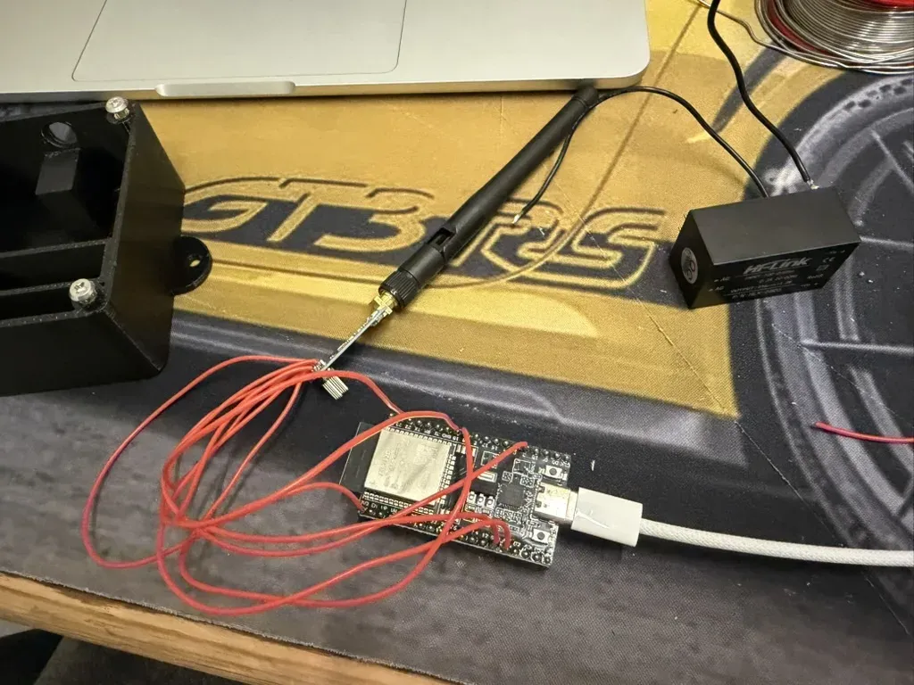
Wiring
The CC1101 board I got has an 8-pin header (2 x 4). This is the pinout from the seller’s picture, and the one I ended up trusting after a round of resoldering:
| CC1101 pin | CC1101 label | ESP32 pin | What it carries |
|---|---|---|---|
| 1 | GND | GND | Ground |
| 2 | VCC | 3V3 | Power, 3.3V only |
| 3 | GDO0 | GPIO4 | Data out to the radio (transmit) |
| 4 | CSN | GPIO22 | SPI chip select |
| 5 | SCK | GPIO18 | SPI clock |
| 6 | MOSI | GPIO23 | SPI data to the radio |
| 7 | MISO / GDO1 | GPIO19 | SPI data from the radio |
| 8 | GDO2 | GPIO27 | Data in from the radio (receive) |
CC1101 header, component side, antenna at the bottom

   7 MISO   5 SCK   3 GDO0   1 GND
   8 GDO2   6 MOSI  4 CSN    2 VCC
Power is just two wires from the Hi-Link to the ESP32:
| Hi-Link | ESP32 |
|---|---|
| +Vo | 5V |
| -Vo | GND |
On the 230V side the cable comes in through a PG7 gland, and live goes through a fuse to one of the Hi-Link’s AC pins, neutral to the other. The ESP32 board makes the 3.3V for itself and the CC1101 from its 5V pin, so the radio never sees 5V.
Here is the whole circuit as a schematic:

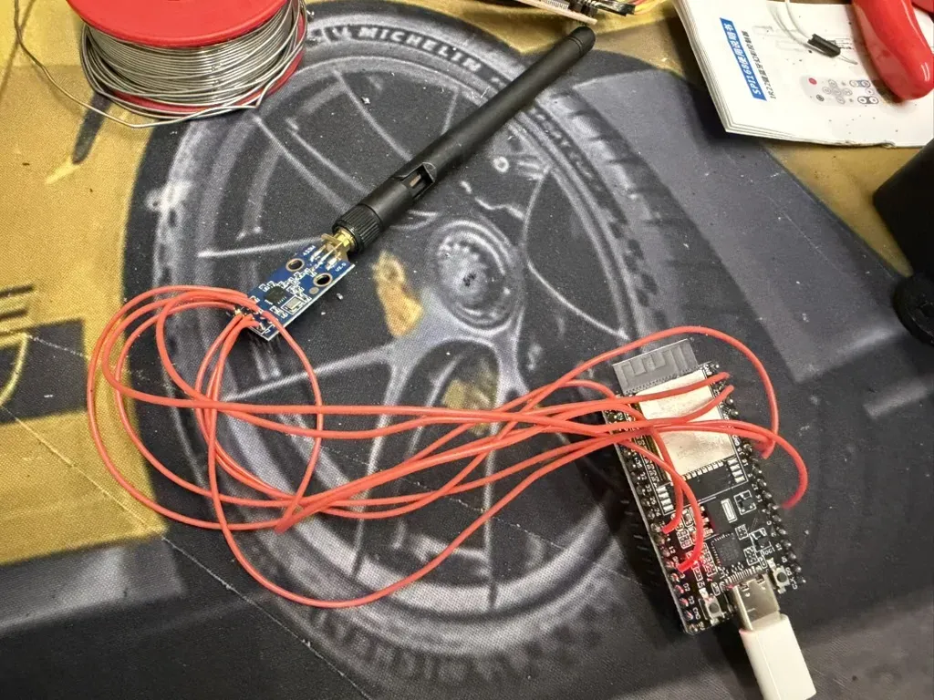
A word of warning about my first attempt: I wired the header from a generic CC1101 diagram, and the ESPHome log told me straight away that it was wrong. At boot the component reads the chip’s part number and version over SPI:
[C][cc1101]:   Chip ID: 0x0F0F
[E][component]:   cc1101 is marked FAILED: unspecified
0x0F0F (and 0x0000 after my first attempt at fixing it) means the ESP32 isn’t really talking to the chip. My header pinout was wrong. After resoldering against the table above it came back with a real answer:
[C][cc1101]:   Chip ID: 0x0014
[C][cc1101]:   Frequency: 433919840 Hz
[C][cc1101]:   Modulation: ASK/OOK
0x0014 is the CC1101’s real part and version number, so if you see that, your SPI wiring is fine.
Sniffing the remote
My first config used ESPHome’s rc_switch dumper, which knows the common 433 MHz remote protocols. I pressed Stop and got a code. I pressed the light button and got the exact same code:
Received RCSwitch Raw: protocol=6 data='00110011111111'
Received RCSwitch Raw: protocol=6 data='00110011111111'
Two buttons can’t send the same thing, so the decoder was guessing. The rc_switch dumper tries its eight built-in protocols and reports the first one that seems to fit. Protocol 6 is an inverted one that fits partial frames easily, and 14 bits is short for a remote like this.
So I switched the receiver to dump raw pulse timings instead, and opened up the filters so it would keep the whole frame:
remote_receiver:
  pin: GPIO27
  dump:
    - raw
  tolerance: 50%
  filter: 100us
  idle: 10ms
Now every press printed a long list of pulse lengths in microseconds. Positive numbers are the carrier on, negative numbers are silence:
Received Raw: 2043, -597, 597, -256, 248, -600, 597, -256, 248, -600, 248, -600, ...The pattern is easy to see once you look at a few of them:
| Part | High | Low |
|---|---|---|
| Header | ~2040 µs | ~600 µs |
| Bit 1 | ~600 µs | ~255 µs |
| Bit 0 | ~250 µs | ~600 µs |
| Gap between repeats | ~5600 µs |
Pressing all the buttons in a row got me a pile of frames and no idea which was which, so I did it one button at a time with a few seconds in between: open, then close, then stop, then light. Turning the timings into bits gave 65-bit frames. The first 48 bits were identical on every button, so that’s the remote’s address. The rest changed per button:
A3 ·· ·· ·· ·· ··  0B  ··  1     open
A3 ·· ·· ·· ·· ··  43  ··  1     close
A3 ·· ·· ·· ·· ··  23  ··  1     stop
A3 ·· ·· ·· ·· ··  AB  ··  1     light
I’ve blanked out my remote’s address bytes and the checksum (which is computed from them). Yours will be different anyway.
A few things fell out of this:
- The frame is
A3, five address bytes, one command byte, one checksum byte and a trailing 1 bit. That layout matches what’s usually called the A-OK protocol, which shows up in a lot of Chinese blind and awning motors. - The checksum is just the sum of the six bytes after
A3, keeping the low byte. It matched every frame I captured. - After Open and Close the remote also sends a short burst of command
0x24, and after the light it sends0xAC. I send those too, so the box behaves exactly like the remote. - The codes don’t change between presses. No rolling code, so replaying them works.
65 bits is also why rc_switch got it wrong. Its decoder tops out at 64 bits, so this protocol was never going to show up there.
The ESPHome config
Since ESPHome doesn’t know this protocol, the config builds the frame itself and sends it with remote_transmitter.transmit_raw. For receiving, an on_raw lambda decodes the pulses back into bytes, checks the address and checksum, and updates Home Assistant.
When someone uses the physical remote, the cover and the light in Home Assistant follow along, and the box doesn’t send anything back. Without that, the light state would drift every time someone grabbed the remote.
Put your own five address bytes into remote_id. The command bytes are the ones from my remote, so sniff yours and check them before you rely on them.
substitutions:
  name: esprf433
  friendly_name: ESPRF433

  rf_frequency: 433.92MHz
  rf_repeat: "6"            # frames per command

  remote_id: "0x00, 0x00, 0x00, 0x00, 0x00"   # the 5 bytes after A3 from YOUR remote
  cmd_open: "0x0B"
  cmd_close: "0x43"
  cmd_stop: "0x23"
  cmd_release: "0x24"       # sent after open/close
  cmd_light: "0xAB"         # light toggle
  cmd_light_release: "0xAC" # sent after the light toggle

  open_time: 30s            # time a full open with a stopwatch
  close_time: 30s

esphome:
  name: ${name}
  friendly_name: ${friendly_name}

esp32:
  board: esp32dev
  framework:
    type: esp-idf

logger:

api:
  encryption:
    key: !secret esprf433_api_key
  actions:
    # Send any command byte from HA (Developer tools > Actions)
    - action: send_command
      variables:
        command: int
      then:
        - script.execute:
            id: send_aok
            cmd: !lambda "return command;"
            release: -1

ota:
  - platform: esphome
    encryption: {}          # uploads use the api encryption key

wifi:
  ssid: !secret wifi_ssid
  password: !secret wifi_password
  ap:
    ssid: "ESPRF433 Fallback"
    password: !secret esprf433_ap_password

captive_portal:

web_server:                 # the little test page on port 80
  port: 80

# ---------------------------------------------------------------- radio

spi:
  clk_pin: GPIO18
  mosi_pin: GPIO23
  miso_pin: GPIO19

cc1101:
  cs_pin: GPIO22
  frequency: ${rf_frequency}
  output_power: 10

remote_transmitter:
  id: rf_tx
  pin: GPIO4                # CC1101 GDO0
  carrier_duty_percent: 100%
  non_blocking: false
  on_transmit:
    then:
      - cc1101.begin_tx
  on_complete:
    then:
      - cc1101.begin_rx

remote_receiver:
  id: rf_rx
  pin: GPIO27               # CC1101 GDO2
  tolerance: 50%
  filter: 100us
  idle: 4ms                 # frames are 5.6 ms apart, so each one arrives on its own
  on_raw:
    then:
      - lambda: |-
          const auto &v = x;
          for (size_t i = 0; i + 1 < v.size(); i++) {
            if (!(v[i] > 1600 && v[i] < 2500 && v[i + 1] < -400 && v[i + 1] > -900)) continue;
            uint8_t b[8] = {0};
            int n = 0;
            size_t j = i + 2;
            while (j + 1 < v.size() && n < 64) {
              int h = v[j], lo = -v[j + 1];
              bool one;
              if (h > 420 && h < 800 && lo > 120 && lo < 420) one = true;
              else if (h > 120 && h < 420 && lo > 420 && lo < 850) one = false;
              else break;
              if (one) b[n / 8] |= 0x80 >> (n % 8);
              n++;
              j += 2;
            }
            i = j;
            if (n < 64 || b[0] != 0xA3) continue;
            const uint8_t rid[5] = {${remote_id}};
            bool mine = true;
            uint8_t sum = b[6];
            for (int k = 0; k < 5; k++) {
              if (b[1 + k] != rid[k]) mine = false;
              sum += b[1 + k];
            }
            if (!mine || sum != b[7]) continue;
            uint8_t cmd = b[6];

            char buf[16];
            snprintf(buf, sizeof(buf), "0x%02X", cmd);
            id(last_rf_code).publish_state(buf);

            // One press arrives as several identical frames
            uint32_t now = millis();
            if (cmd == id(last_rx_cmd) && now - id(last_rx_ms) < 1000) {
              id(last_rx_ms) = now;
              continue;
            }
            id(last_rx_cmd) = cmd;
            id(last_rx_ms) = now;

            // Mute the transmitter briefly so state updates don't re-send RF
            id(tx_block_start) = now;
            id(tx_block_len) = 800;
            if (cmd == ${cmd_open}) id(louvers).make_call().set_command_open().perform();
            else if (cmd == ${cmd_close}) id(louvers).make_call().set_command_close().perform();
            else if (cmd == ${cmd_stop}) id(louvers).make_call().set_command_stop().perform();
            else if (cmd == ${cmd_light}) id(pergola_light).toggle().perform();
          }

globals:
  # No transmissions for 10 s after boot, so restoring state sends nothing
  - id: tx_block_start
    type: uint32_t
    initial_value: "0"
  - id: tx_block_len
    type: uint32_t
    initial_value: "10000"
  - id: last_rx_cmd
    type: int
    initial_value: "-1"
  - id: last_rx_ms
    type: uint32_t
    initial_value: "0"

script:
  # Send one remote command, then its release frame (release < 0: none)
  - id: send_aok
    mode: queued
    parameters:
      cmd: int
      release: int
    then:
      - if:
          condition:
            lambda: "return millis() - id(tx_block_start) >= id(tx_block_len);"
          then:
            - remote_transmitter.transmit_raw:
                transmitter_id: rf_tx
                code: !lambda |-
                  const uint8_t rid[5] = {${remote_id}};
                  uint8_t b[8] = {0xA3, rid[0], rid[1], rid[2], rid[3], rid[4], (uint8_t) cmd, 0};
                  for (int k = 1; k < 7; k++) b[7] += b[k];
                  std::vector<int32_t> v = {2040, -600};
                  for (int n = 0; n < 64; n++) {
                    bool one = b[n / 8] & (0x80 >> (n % 8));
                    v.push_back(one ? 600 : 250);
                    v.push_back(one ? -255 : -600);
                  }
                  v.push_back(600);
                  v.push_back(-5600);
                  return v;
                repeat:
                  times: ${rf_repeat}
            - if:
                condition:
                  lambda: "return release >= 0;"
                then:
                  - remote_transmitter.transmit_raw:
                      transmitter_id: rf_tx
                      code: !lambda |-
                        const uint8_t rid[5] = {${remote_id}};
                        uint8_t b[8] = {0xA3, rid[0], rid[1], rid[2], rid[3], rid[4], (uint8_t) release, 0};
                        for (int k = 1; k < 7; k++) b[7] += b[k];
                        std::vector<int32_t> v = {2040, -600};
                        for (int n = 0; n < 64; n++) {
                          bool one = b[n / 8] & (0x80 >> (n % 8));
                          v.push_back(one ? 600 : 250);
                          v.push_back(one ? -255 : -600);
                        }
                        v.push_back(600);
                        v.push_back(-5600);
                        return v;
                      repeat:
                        times: 3

# ---------------------------------------------------------------- entities

cover:
  - platform: time_based
    id: louvers
    name: Pergola Louver
    device_class: curtain
    assumed_state: true
    has_built_in_endstop: true   # the motor stops itself at the ends
    open_action:
      - script.execute:
          id: send_aok
          cmd: ${cmd_open}
          release: ${cmd_release}
    open_duration: ${open_time}
    close_action:
      - script.execute:
          id: send_aok
          cmd: ${cmd_close}
          release: ${cmd_release}
    close_duration: ${close_time}
    stop_action:
      - script.execute:
          id: send_aok
          cmd: ${cmd_stop}
          release: -1

output:
  # The remote has one light button that toggles, so on and off both send it
  - platform: template
    id: light_rf_out
    type: binary
    write_action:
      - script.execute:
          id: send_aok
          cmd: ${cmd_light}
          release: ${cmd_light_release}

light:
  - platform: binary
    id: pergola_light
    name: Pergola Light
    output: light_rf_out
    restore_mode: RESTORE_DEFAULT_OFF

text_sensor:
  - platform: template
    id: last_rf_code
    name: Last RF code
    entity_category: diagnostic
    update_interval: never

sensor:
  - platform: wifi_signal
    name: WiFi signal
    update_interval: 60s

button:
  - platform: restart
    name: Restart
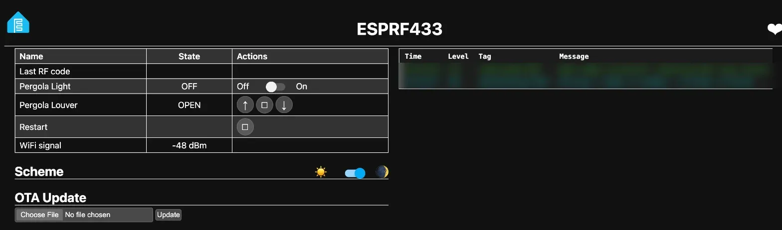
In Home Assistant this shows up as a cover called Pergola Louver with open, close and stop, a light called Pergola Light, and a diagnostic sensor with the last code it heard. The cover’s device class is curtain, so Home Assistant shows it with a curtain icon. There’s also a send_command action for testing any command byte from Developer tools. Both entities go on to Apple Home through the HomeKit bridge like everything else.
The box also serves ESPHome’s small web page, which is handy for testing without Home Assistant:
The cover uses ESPHome’s time_based platform, so the position is estimated from how long the motor has been running. Time a full open and a full close with a stopwatch and put those numbers in open_time and close_time.
The case
I designed the case in Fusion 360 as a parametric script, so I could change a dimension and rebuild the whole thing. It’s 120.8 x 80.8 x 39.6 mm, printed in PETG on my X1C.
The left side holds the Hi-Link in a cradle and has a solid wall between it and the low-voltage side, with just a notch at the top for the 5V pair. The right side has pedestals for the ESP32 (it sits on its headers, pins down) and the CC1101, whose SMA connector goes through the back wall so the antenna screws on outside. Four bosses take M3 heat-set inserts, and the lid has little keeper posts underneath that stop the boards lifting when it’s closed. There are two zip-tie anchors on the mains side and ears for screwing it to the wall.
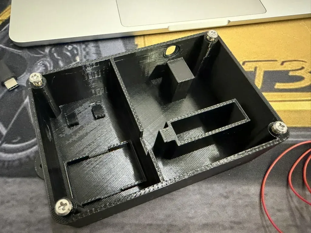
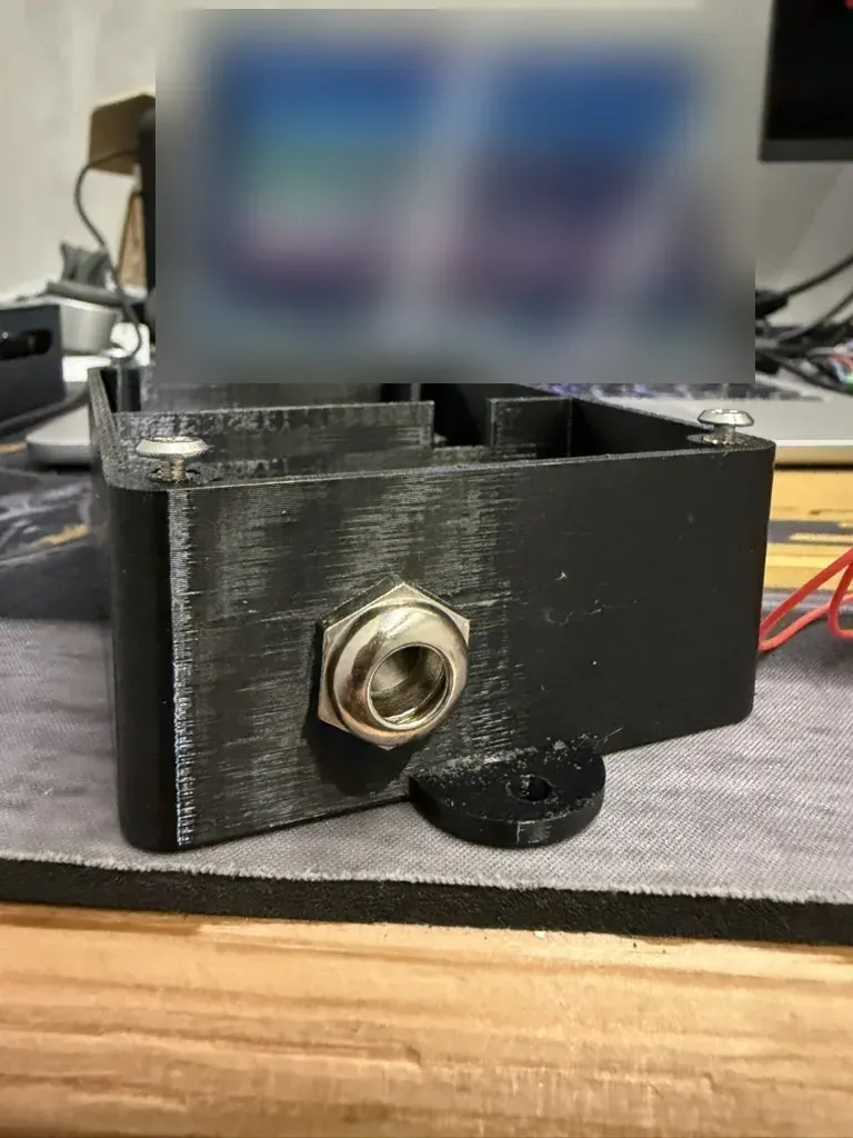
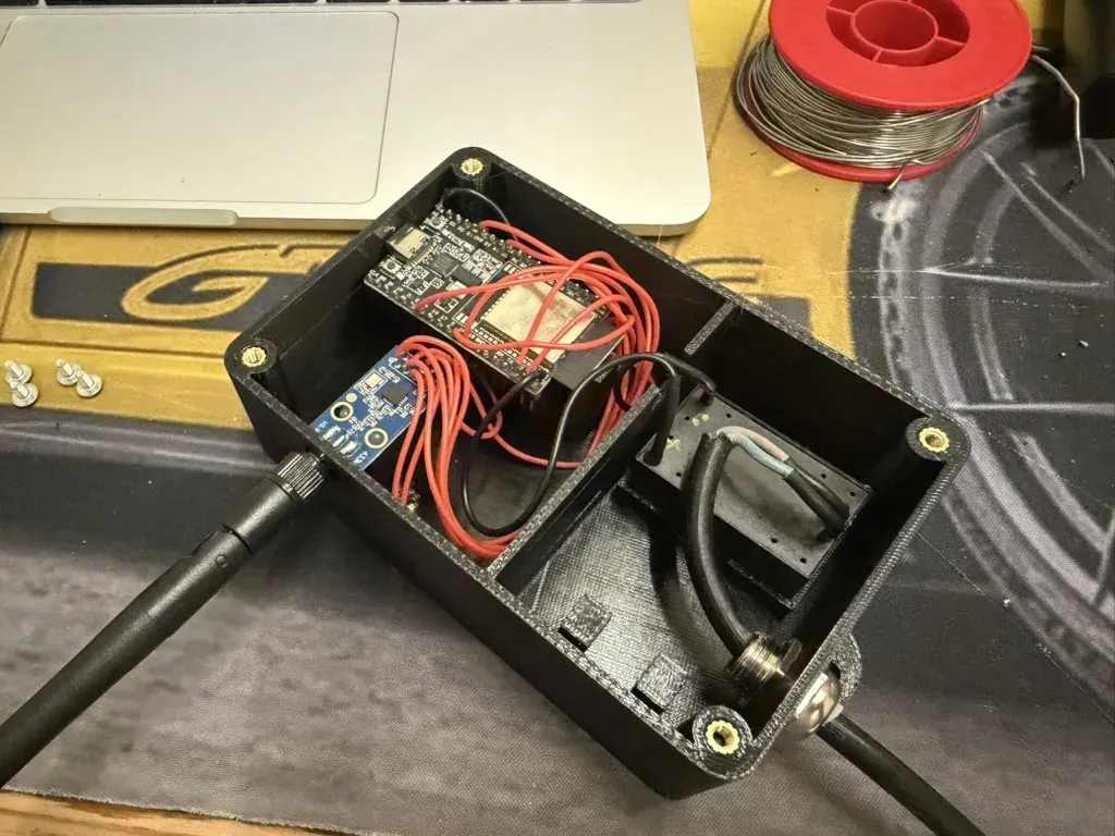
The print files are on my MakerWorld profile as ESPRF433 case for ESP32, CC1101 and HLK-5M05.
Was it worth it
For about $18.50 in parts and an evening of sniffing, the pergola now opens from my phone, from an automation, or from Siri, and the old remote still works and keeps Home Assistant in sync. The CC1101 is also listening to everything on 433 MHz now, so if another cheap remote shows up at home, I already know how to deal with it.
| Part | Price (USD) |
|---|---|
| ESP32 | ~$7.50 |
| CC1101 | ~$5.50 |
| Hi-Link HLK-5M05 | ~$5.50 |
| Total | ~$18.50 |
Follow along. New posts show up on the RSS feed. I also share my projects on GitHub, MakerWorld and LinkedIn.