
In this post
I wheel with a small group, and once we leave the pavement there is usually no cell signal. We already carry handheld radios for talking. Meshtastic adds texts and shared positions over LoRa radio with no network at all, and a node costs about as much as a few modules. So I built one for the Jeep from parts and printed a case for it.
I started from Adrelien’s guide, Meshtastic DIY: How To Build Your Own Meshtastic Node (ESP32 & LoRa Radio). It covers the basic ESP32 plus LoRa build well, so I’ll only go into detail where mine differs: a different radio module, a GPS, 12 V power and my own housing.
What went into the box
| Module | What it does | Price (USD) |
|---|---|---|
| ESP32 dev board (ESP32-WROOM-32, USB-C) | Runs the Meshtastic firmware, Bluetooth to the phone | ~$4 |
| XL1278-SMT LoRa module (SX1278, 433 MHz) | The radio | ~$3 |
| u-blox NEO-6M GPS module with ceramic patch antenna | Position for the map | ~$3 |
| DC-DC step-down (buck) converter | Jeep 12V down to 5V for the ESP32 | ~$2 |
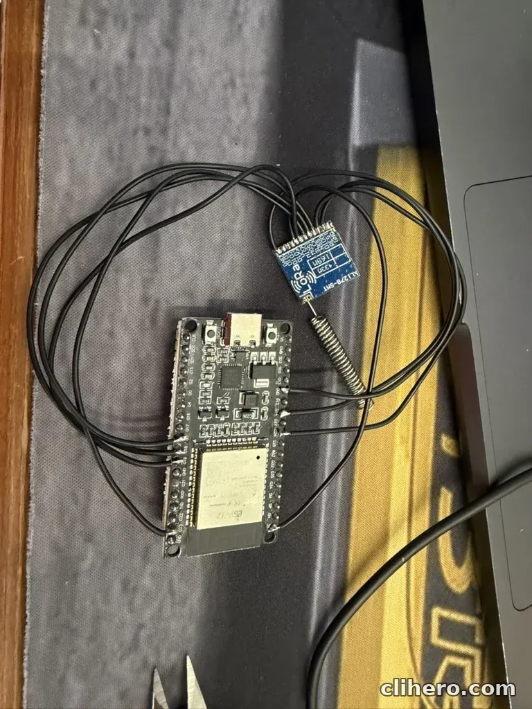
That is about $12 in modules. On top of that come a 433 MHz helical spring antenna soldered straight to the radio’s antenna pad, a round rocker switch for power, and thin hookup wire. Everything is soldered, with no jumper leads.
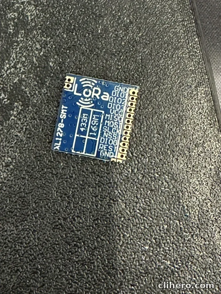
The guide uses an Ra-02 module. Mine is an XL1278-SMT, which has the same SX1278 chip on a smaller board with castellated edges and no antenna connector. That means soldering wires directly to the pads and soldering the antenna on as well. It’s fiddly work, but the result is small and nothing can shake loose.
There is no screen on this build. I left it out to keep the box simple, and it cost me some time later when I tried to pair the phone.
Wiring
The firmware target for a build like this is called DIY V1, and it expects the radio and GPS on fixed pins. I wired to match it:
| Module pin | ESP32 pin |
|---|---|
| LoRa VCC | 3V3 |
| LoRa GND | GND |
| LoRa SCK | GPIO5 |
| LoRa MISO | GPIO19 |
| LoRa MOSI | GPIO27 |
| LoRa NSS | GPIO18 |
| LoRa RESET | GPIO23 |
| LoRa DIO0 | GPIO26 |
| LoRa DIO1 | GPIO33 |
| LoRa DIO2 | GPIO32 |
| GPS TX | GPIO12 (firmware’s GPS RX) |
| GPS RX | GPIO15 (firmware’s GPS TX) |
Two things to watch. The SX1278 is a 3.3 V part, so it goes on the 3V3 pin and never on 5 V. And the radio must not transmit without an antenna attached, so solder the antenna before the first power-up.
Here is the whole circuit as a schematic:
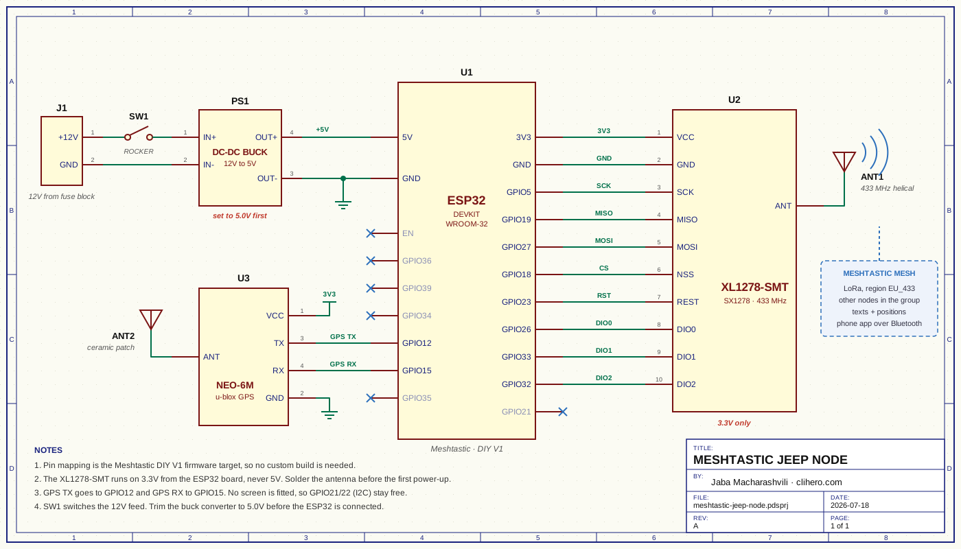
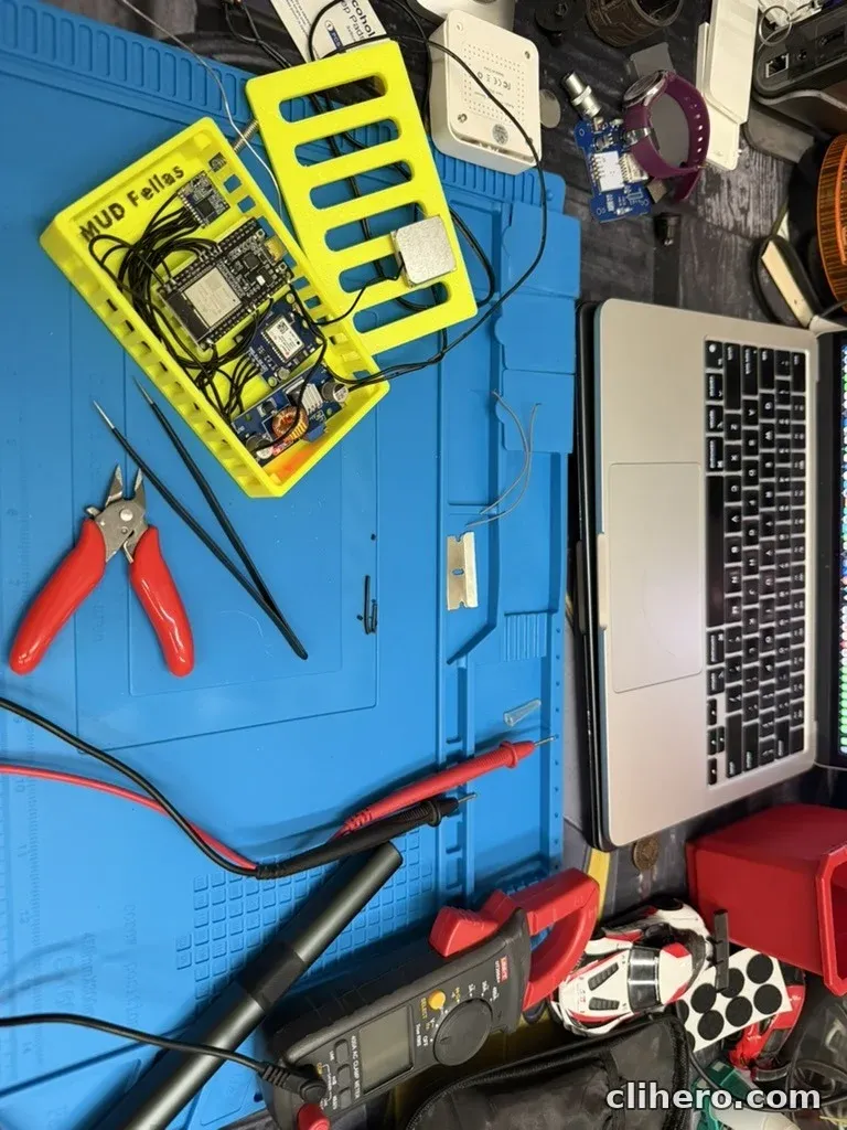
The buck converter goes in last. Set its output to 5 V with a multimeter before connecting it to the ESP32, because these boards ship with the trimmer set to anything.
Flashing and first setup
Flashing is the easy part. Open the Meshtastic web flasher in Chrome, pick the DIY V1 device, choose the latest stable release and flash over USB. After the reboot I set the region to EU_433 to match the module.
Then I tried to pair my phone and it asked for a PIN. By default the node generates a random PIN for every pairing attempt and shows it on its screen. Mine has no screen. The fix is to connect over USB serial with the web client, go to the Bluetooth config and change the pairing mode to fixed PIN with a code of your own. The same thing from the CLI:
meshtastic --set bluetooth.mode FIXED_PIN --set bluetooth.fixed_pin 123456Pick something other than 123456.
The GPS needed attention too. On a DIY build it is off until you set GPS mode to enabled in the position settings, and “fixed position” has to be off or the node keeps reporting the same coordinates forever. A first fix also needs open sky and can take several minutes, so don’t judge it on the bench.
The Meshtastic case
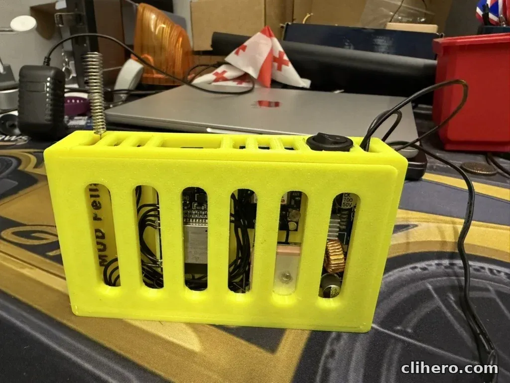
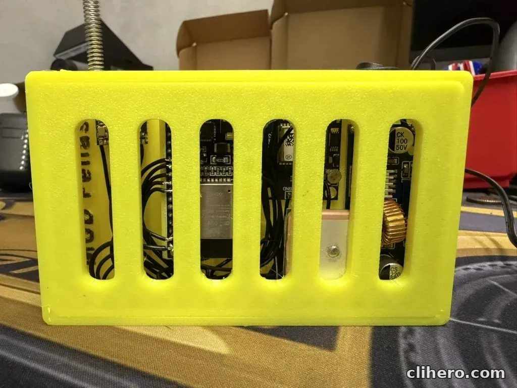
The housing is my own design. I modeled it around these exact boards, so each one has its own spot on the floor of the box and there is room to tuck the extra wire away. “MUD Fellas” is printed into the floor.
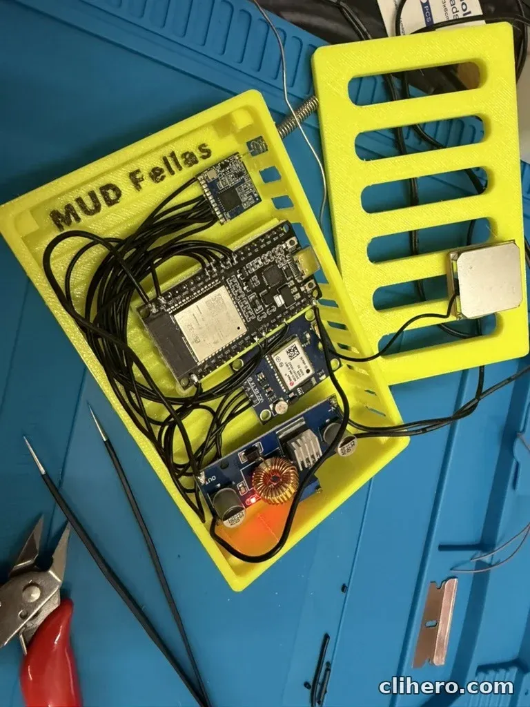
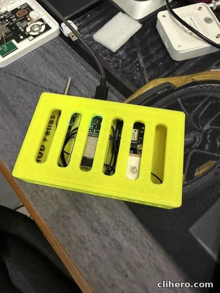
The lid and all four walls are slotted. A buck converter and an ESP32 in a closed box inside a car in summer get hot, and the slots also let me see the status LEDs without opening anything. The GPS patch antenna sits right under the lid, facing up.
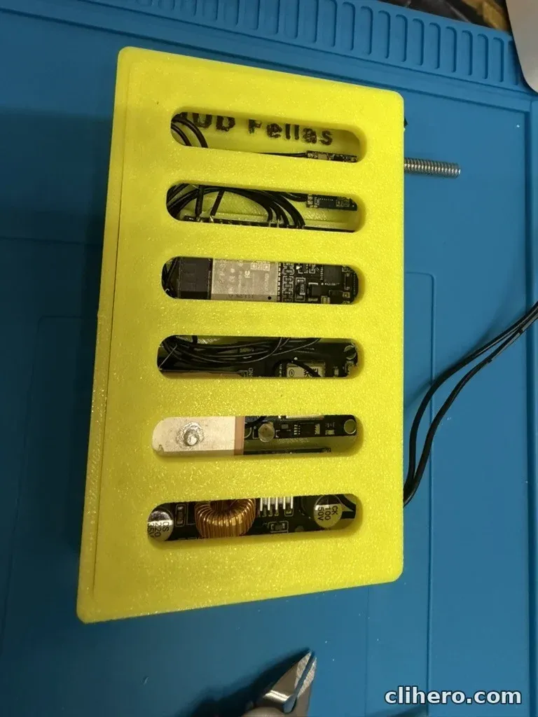
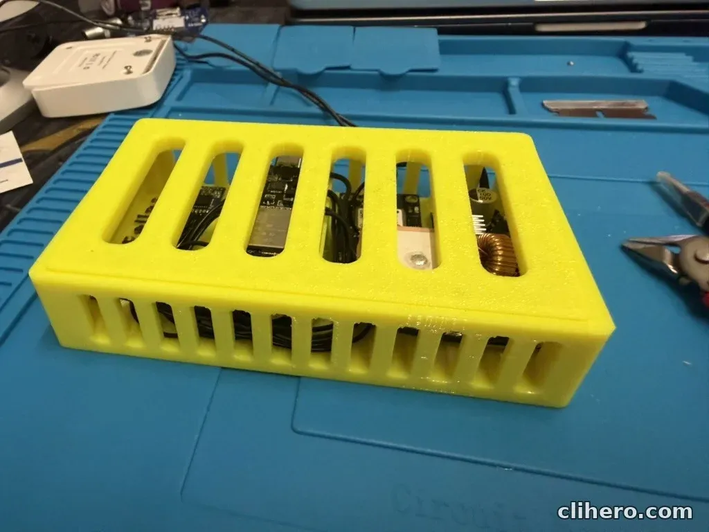
The antenna comes out through a hole in the corner and the 12 V lead leaves through a slot in the wall.
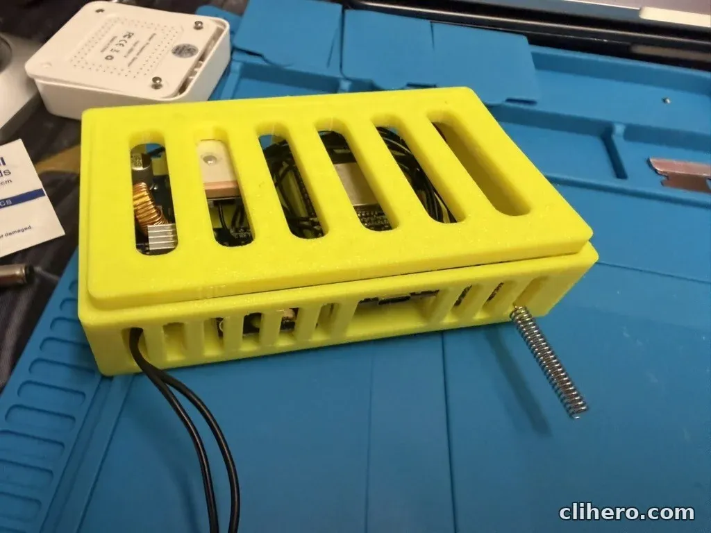
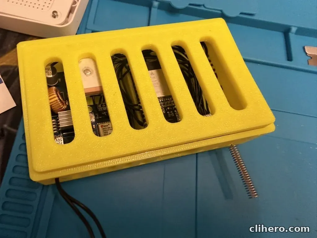
The top edge has the power switch and an opening for the ESP32’s USB-C port, so I can update the firmware or change settings over serial without taking the node apart.
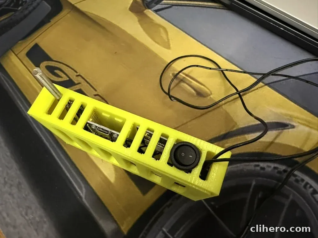
It stands upright with the antenna pointing up, which is how it sits in the car.
In the Jeep
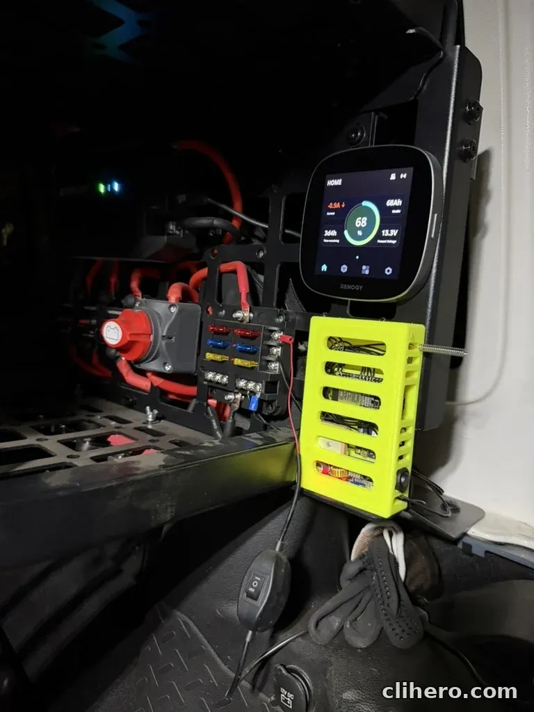
The node lives in the back, on the power panel with the fuse block and the Renogy ONE Core. It takes 12 V from the fuse block, so it runs from the house battery and stays up when the engine is off.
I flip the rocker switch, the node boots, and from the driver’s seat I use the Meshtastic app on my phone over Bluetooth.
Was it worth it
For a handful of cheap modules and some fiddly soldering, yes. I now have a node that is wired into the car, reports its own position and needs nothing from me except a flick of the switch. A ready-made board with a screen would have been quicker and would have saved me the pairing problem, but it would not have fit my panel or run from 12 V without more boxes around it.
Follow along. New posts show up on the RSS feed. I also share my projects on GitHub, MakerWorld and LinkedIn.