
In this post
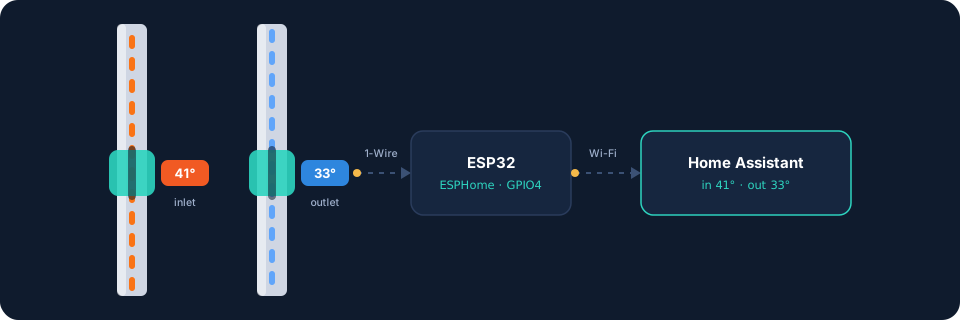
My heating manifold has a dial thermometer on every circuit. They look great and tell you nothing unless you are standing in front of them.
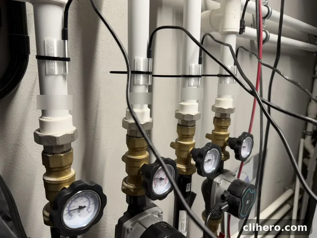
I wanted those numbers in Home Assistant: what goes into each floor’s loop and what comes back. The gap between the two tells you whether a circuit is actually delivering heat or just circulating warm water. I did not want to cut into the pipes or call a plumber, so everything here clips on from the outside.
The sensors
The probes are DS18B20s in stainless steel tubes, the waterproof kind with a long cable. The DS18B20 is a Dallas (now Maxim, now Analog Devices) part, which is why ESPHome calls the platform dallas_temp. Each one has a unique 64-bit address, so you can hang several on a single data wire and the ESP32 tells them apart.
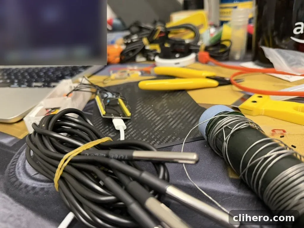
I used four: inlet and outlet on the floor 0 pump circuit, inlet and outlet on floor 2.
Joining four probes onto one bus
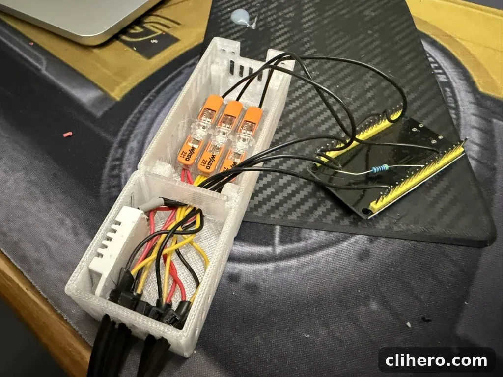
All four probes share the same three lines: power, ground and data. Three WAGO 221 connectors do the joining, one per line, with every probe’s wire for that line going into the same WAGO. No soldering, and I can swap a probe in a minute.
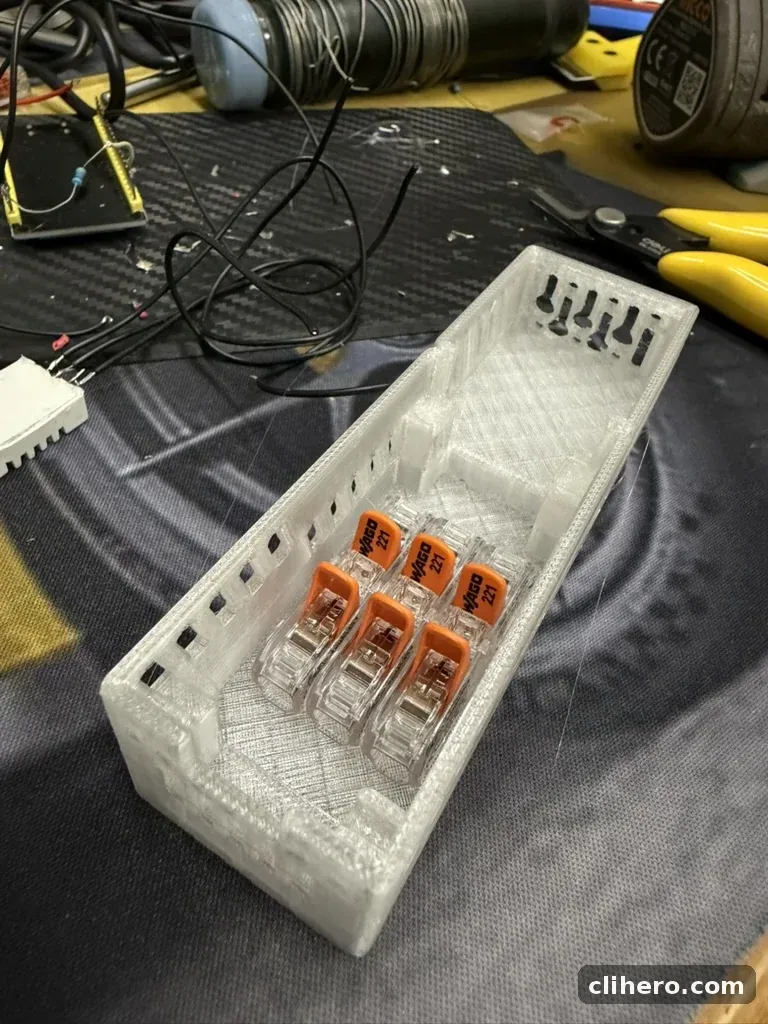
The data line needs a pull-up resistor to 3.3 V. 4.7 kΩ is the usual value for this.
Here is the whole circuit as a schematic:

The enclosure
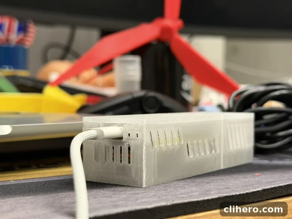
I printed a two-part box. One half holds the ESP32 with its USB-C port open at the end. The other half holds the WAGOs, the cable entries and a DHT22 for the room’s temperature and humidity. Both halves are vented, so the DHT22 reads the room rather than the board’s own heat.
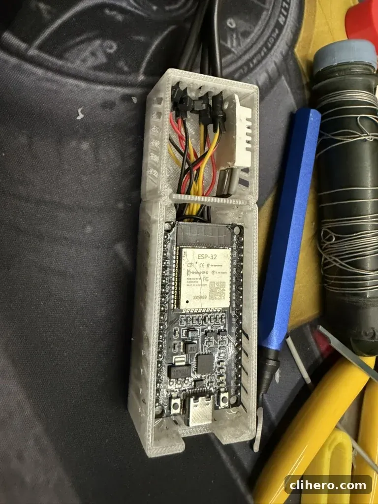
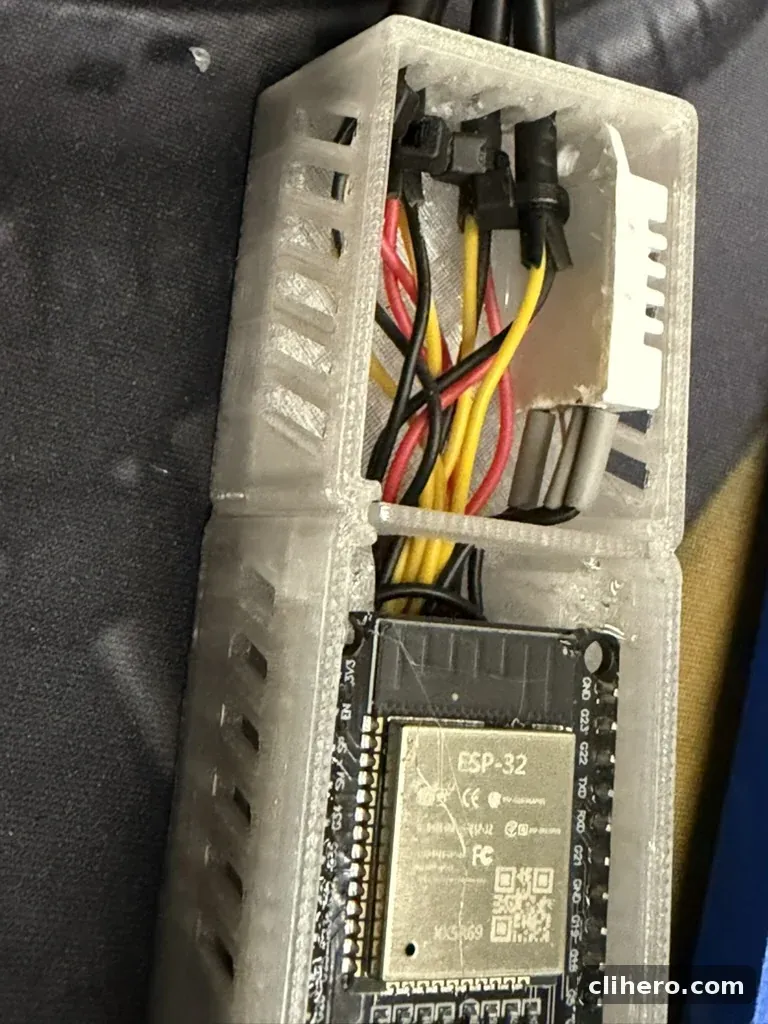
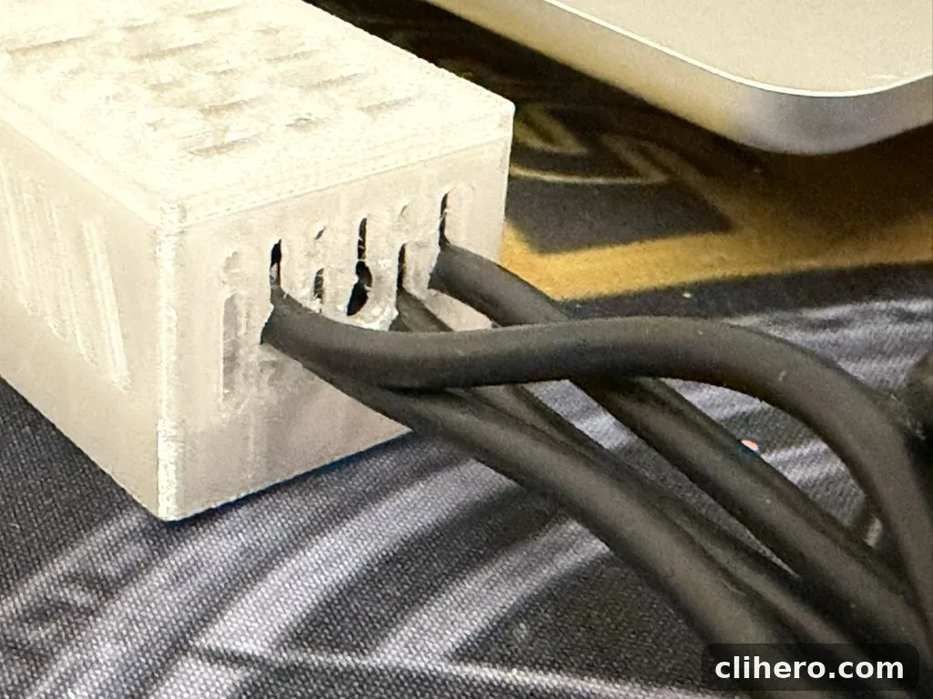
The probe cables come out through slots in the end wall, which also act as strain relief.
The clips
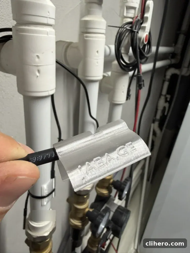
A round probe on a round pipe touches along one thin line, and if it shifts a few millimetres it reads the air instead of the pipe. So I printed a curved saddle that matches the pipe, with a groove down the middle that holds the probe flat against the surface.
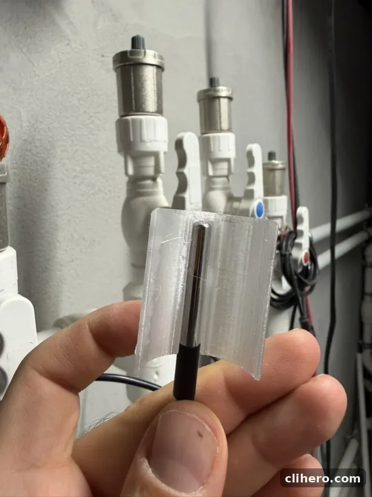
A zip tie around the clip holds it all on the pipe. The clip spreads the pressure, so the tie can be tight without pinching the probe.
The ESPHome config
The whole device is one short file. The four probes sit on a single one_wire bus on GPIO4, and the DHT22 is on GPIO23.
esphome:
  name: esp32-tech-multisensor
  friendly_name: ESP32 Tech Multisensor

esp32:
  board: esp32dev
  framework:
    type: esp-idf

logger:

web_server:
  port: 80

one_wire:
  - platform: gpio
    pin: GPIO4
    id: onewire_bus

sensor:
  - platform: dht
    pin: GPIO23
    model: DHT22
    temperature:
      name: "Tech Room Temperature"
    humidity:
      name: "Tech Room Humidity"
    update_interval: 10s

  - platform: dallas_temp
    one_wire_id: onewire_bus
    address: 0xd2785fd446998328
    name: "Floor 0 Pump Outlet Temperature"
    resolution: 12
    update_interval: 10s

  - platform: dallas_temp
    one_wire_id: onewire_bus
    address: 0x7273d6d446132228
    name: "Floor 0 Pump Inlet Temperature"
    resolution: 12
    update_interval: 10s

  - platform: dallas_temp
    one_wire_id: onewire_bus
    address: 0x9078d6d446416a28
    name: "Floor 2 Pump Outlet Temperature"
    resolution: 12
    update_interval: 10s

  - platform: dallas_temp
    one_wire_id: onewire_bus
    address: 0xf378dad446e8cc28
    name: "Floor 2 Pump Inlet Temperature"
    resolution: 12
    update_interval: 10s

api:
  encryption:
    key: !secret api_key

ota:
  - platform: esphome
    password: !secret ota_password

wifi:
  ssid: !secret wifi_ssid
  password: !secret wifi_password
  ap:
    ssid: !secret fallback_ssid
    password: !secret fallback_password

captive_portal:
The addresses are specific to my probes. To find yours, flash the config with just the one_wire block and no sensors. ESPHome prints every address it finds on the bus to the log, and you copy them in. Warm one probe in your hand and watch which reading moves to figure out which address is which.
A note on accuracy
A probe on the outside of a plastic pipe does not read the water temperature. PVC is a decent insulator, so the surface runs a few degrees cooler than the water inside. I tried per-sensor offsets with a lambda filter to correct for it, and ended up leaving them out.
What I care about is the difference between inlet and outlet, and both probes on a circuit sit on the same kind of pipe in the same kind of clip. Their errors are close enough that the gap between them is still meaningful. If you need the true water temperature, you want an immersion sensor in a thermowell, and that means opening the pipe.
In Home Assistant
ESPHome shows up in Home Assistant on its own, and the four probes become normal temperature sensors. I put them on my heating dashboard as inlet and outlet tiles per floor, with a 24-hour graph underneath.
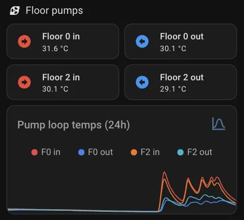
When the inlet and outlet lines sit on top of each other, that circuit is circulating but not heating anything. When they spread apart, the floor is taking heat. I wrote up the whole dashboard, with the YAML, in part 2 of my boiler series.
Follow along. New posts show up on the RSS feed. I also share my projects on GitHub, MakerWorld and LinkedIn.