
In this post
- The serial console that only talked one way
- The RX pin was dead
- The plan: skip the CPU, talk to the flash chip
- Wiring the ESP32 directly to the chip
- The ESP32 sketch
- Dumping the firmware
- Reading the map
- Getting into the filesystem — and the trap that bricked it once
- Backdooring the rootfs
- Repacking, and the one rule that matters
- Reassembling the full image
- Why the camera can’t say no
- Writing it back
- Powering on
- What I did differently from the tutorial
- Coming in part two
- A few honest warnings
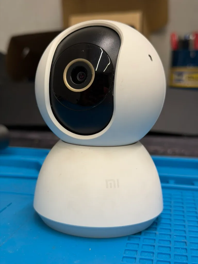
I have a cheap Xiaomi camera — a Mi 360° Home Security Camera 2K, model MJSXJ09CM — that takes perfectly good pictures and then insists on shipping them to a cloud I never asked for.
What I wanted was boring: no cloud, no app, the camera answering to me instead of to a server on the far side of the world. The clean way there is a root shell. Once you’re root you own the box — you can kill the phone-home and stop asking anyone’s permission. Getting that shell is this post. Actually using it is the next one.
The usual way to get that shell is the serial console: solder onto the UART pads, interrupt the bootloader, drop into a shell. I started down exactly that road, following this excellent writeup from sungurlabs, which is where I first learned this camera was even hackable.
Then my plan hit a wall. Literally a dead pad.
The serial console that only talked one way
First I had to get inside. The camera pops apart into the pan/tilt base and the head, and the interesting board is behind the lens.
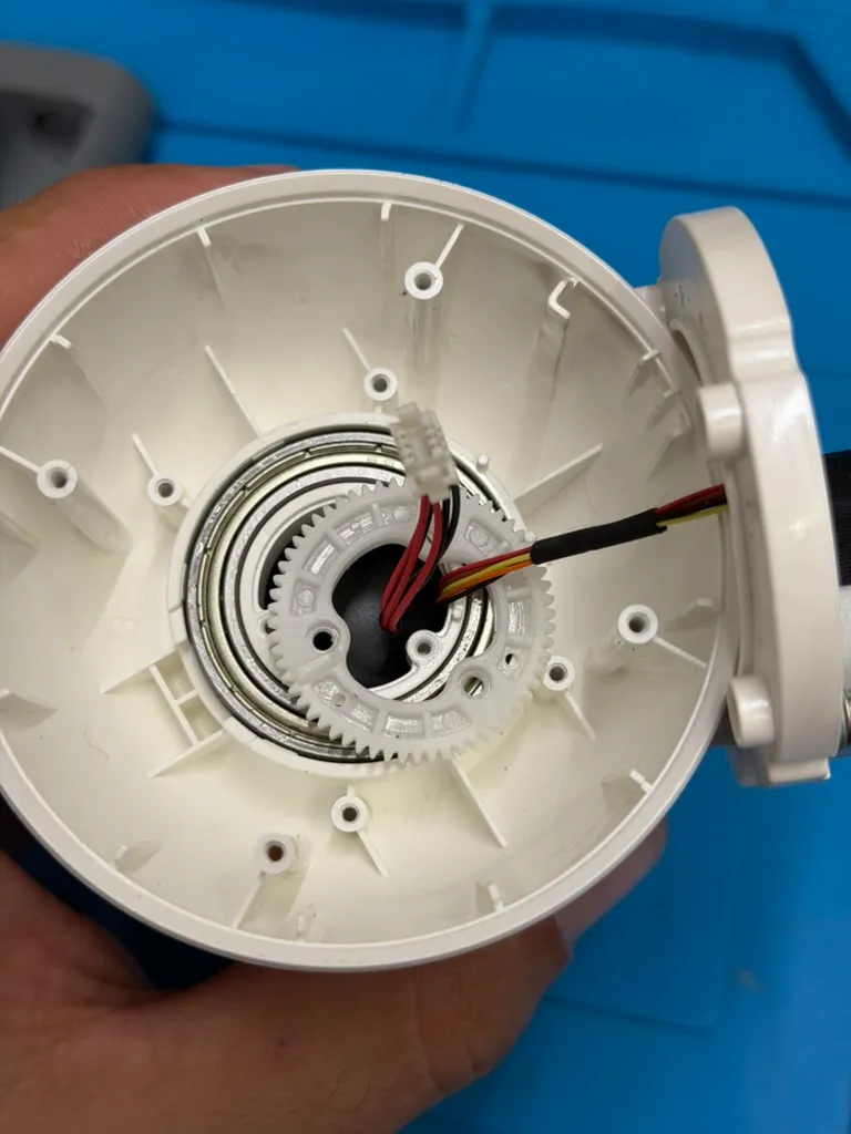
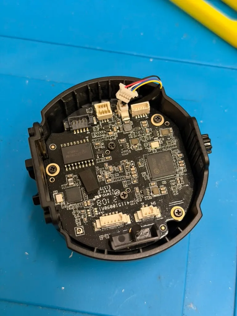
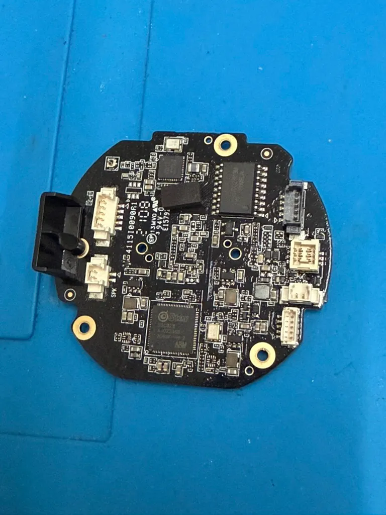
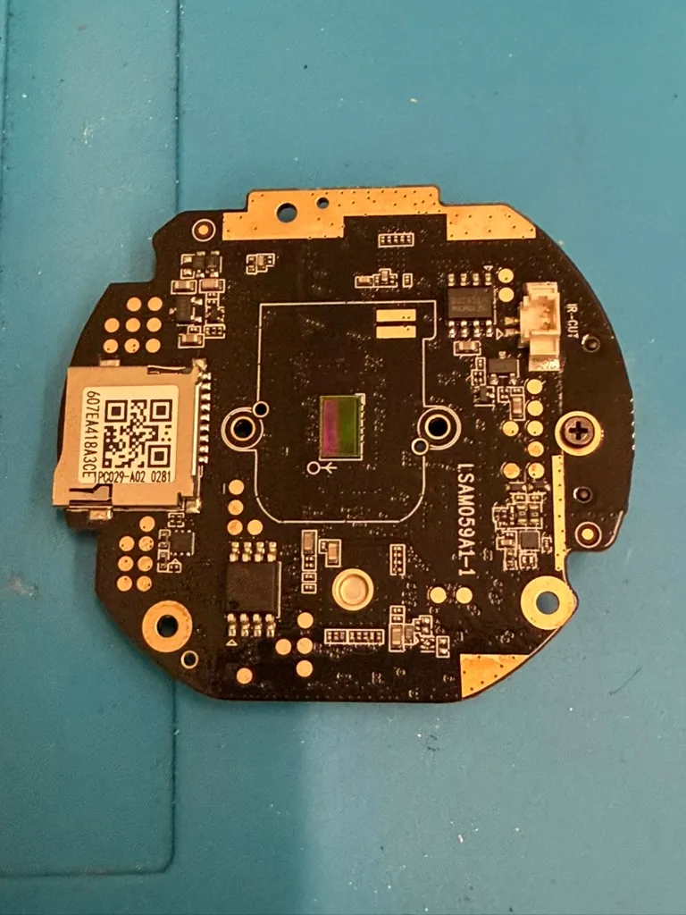
One thing before you copy anyone’s addresses, mine included: this isn’t the Ingenic camera from the tutorial. Mine is a SigmaStar SoC (an Infinity6-class part, I6gc677ccb) on an IPC029A02 board. Close enough that the ideas carry over, different enough that none of the exact offsets do.
I soldered flying leads onto the three UART pads (TX, RX, GND) and hooked up a USB-to-serial adapter at 115200 8N1.
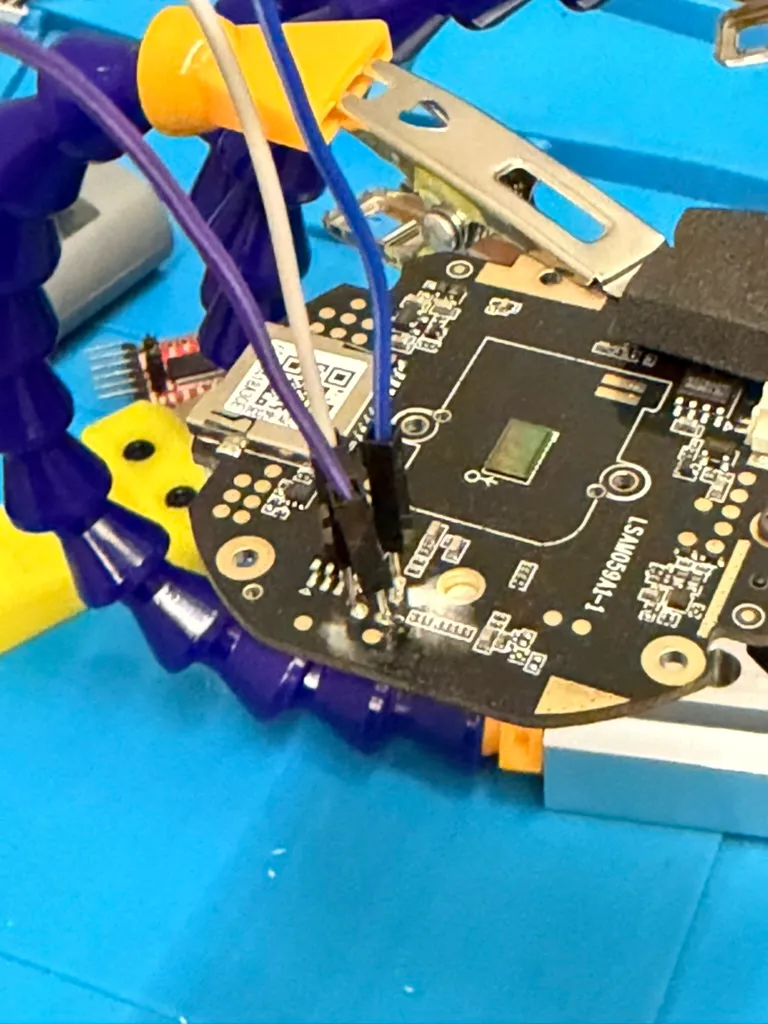
Boot logs streamed out beautifully. The SigmaStar ROM loader, the custom bootloader, the kernel handoff, the whole Linux userspace coming up and grabbing a DHCP lease — all of it, live:
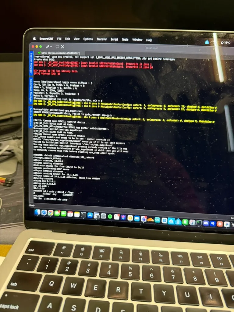
So TX — the camera talking to me — worked. Great.
The problem was RX, me talking back to the camera. Nothing I typed did anything. Bytes went out of my adapter and just vanished.
The RX pin was dead
I checked the obvious stuff first: swapped the adapter, crossed and un-crossed TX/RX, tried a different ground. Then I measured the RX pad to ground with the board powered off and got about 105 Ω. A healthy pad reads open. 105 Ω to ground means the pad had lifted and the trace was damaged — probably my own fault, an earlier soldering session with too much heat. TX in, nothing back out.
There was a second nail in the coffin I only spotted later, reading the u-boot environment out of the dump: bootdelay=0. There’s no “hit any key” prompt to catch on this board even with a perfect RX line. Between the dead pad and the zero delay, the serial console was never going to let me stop the boot.
A console you can read but not type into is useless for interrupting a bootloader. I could have gone hunting for the RX signal further upstream and tried to tap it, but honestly, that felt like fighting the problem instead of solving it.
So I stopped trying to talk to the CPU and dropped a layer down, straight to where the firmware actually lives.
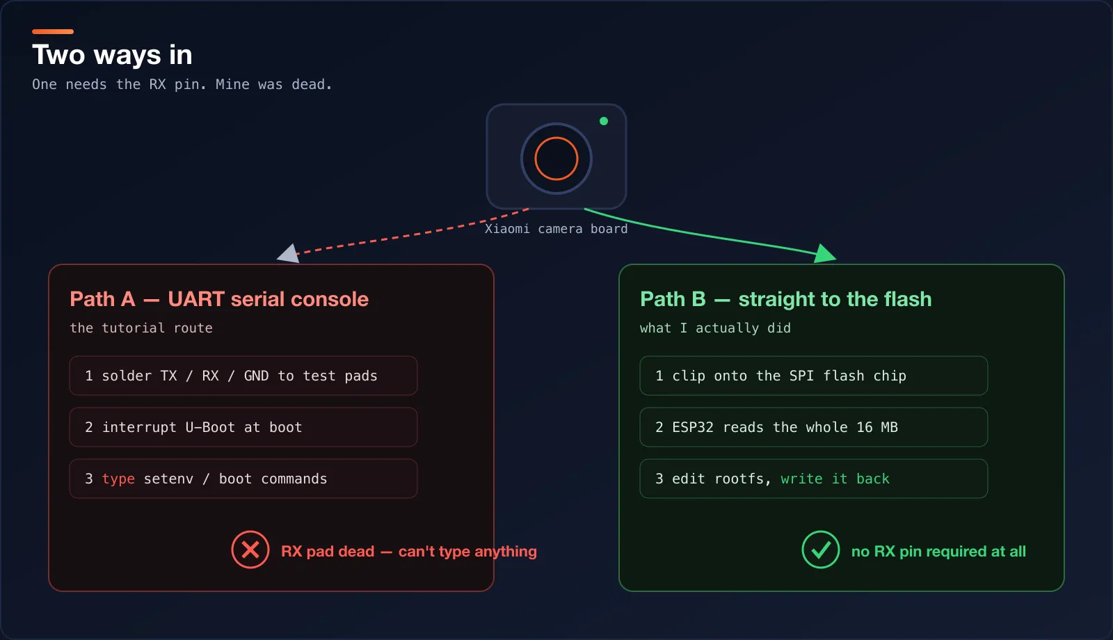
The plan: skip the CPU, talk to the flash chip
Everything this camera knows about itself — the bootloader, the kernel, the whole filesystem — sits in one little 8-pin chip: an SPI NOR flash. Under a macro lens the markings are clear: a Macronix 25L12833F, i.e. an MX25L12833F, 16 MB. (If you want the pinout and timings, the Macronix datasheet is worth a look.)
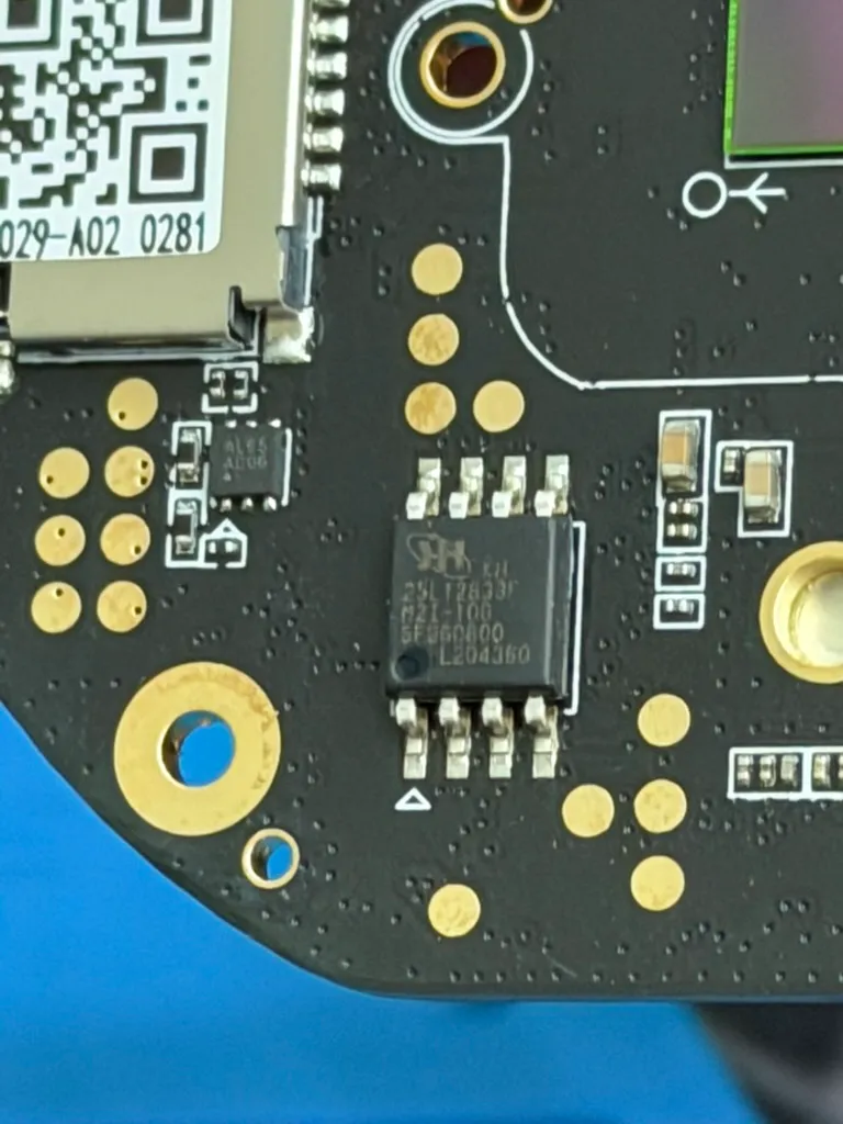
The good part is that this chip doesn’t care about the CPU, the fried RX pad, or the bootloader. It’s a plain SPI device. If I can read it and write it directly, I can:
- dump the entire firmware to my PC,
- edit the filesystem to give myself a root shell,
- write it straight back onto the chip.
No serial console. No RX pin. The CPU wakes up later and just runs whatever I left on the flash.
And the tool I used to talk to the chip wasn’t a fancy programmer. It was an ESP32 I already had in a drawer.
Wiring the ESP32 directly to the chip
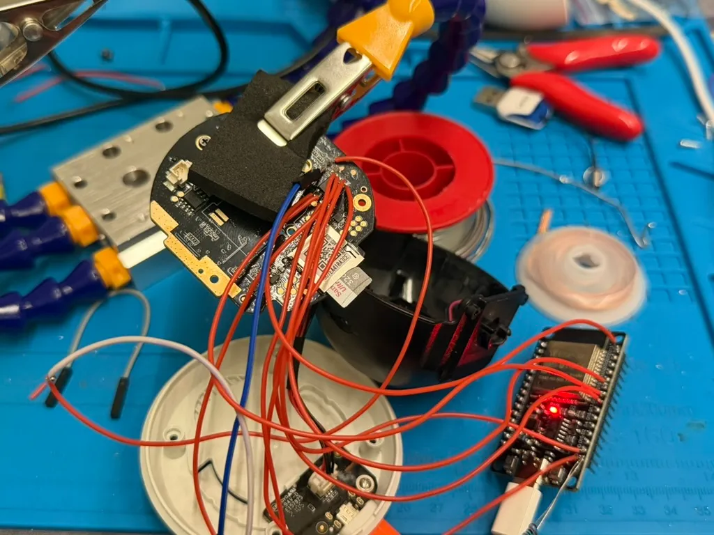
The MX25L12833F is a standard SOIC-8 part, so the pinout is the one every 25-series flash uses. I ran the eight legs over to the ESP32’s hardware SPI pins with flying leads soldered straight to the chip.
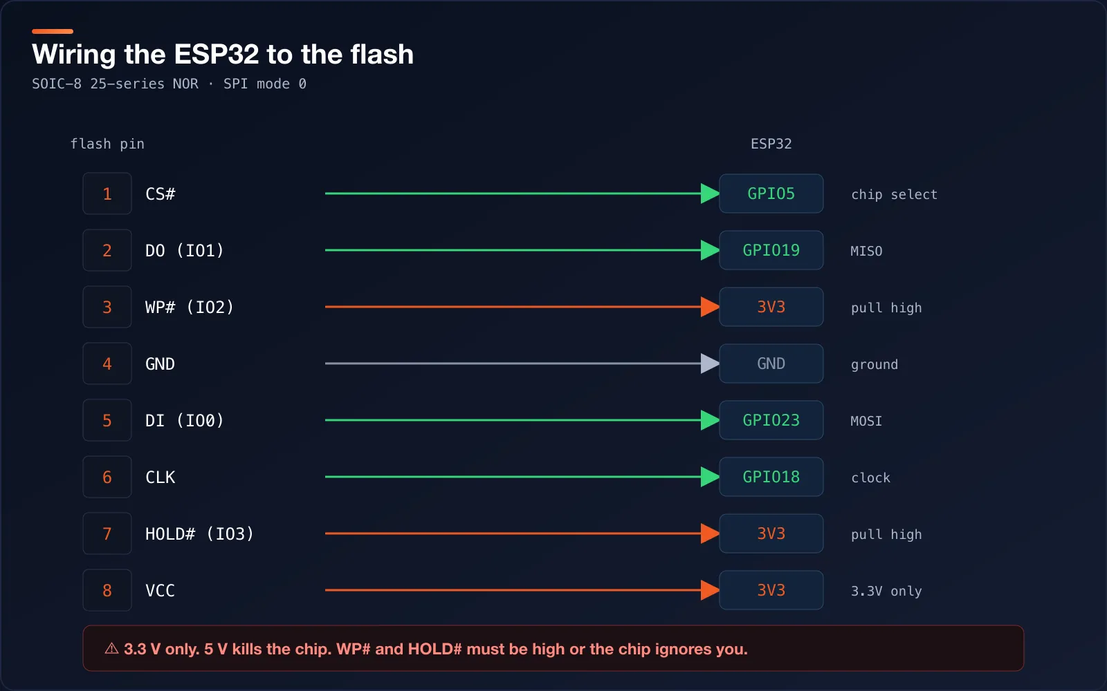
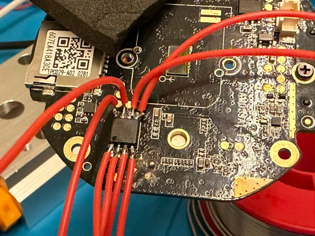
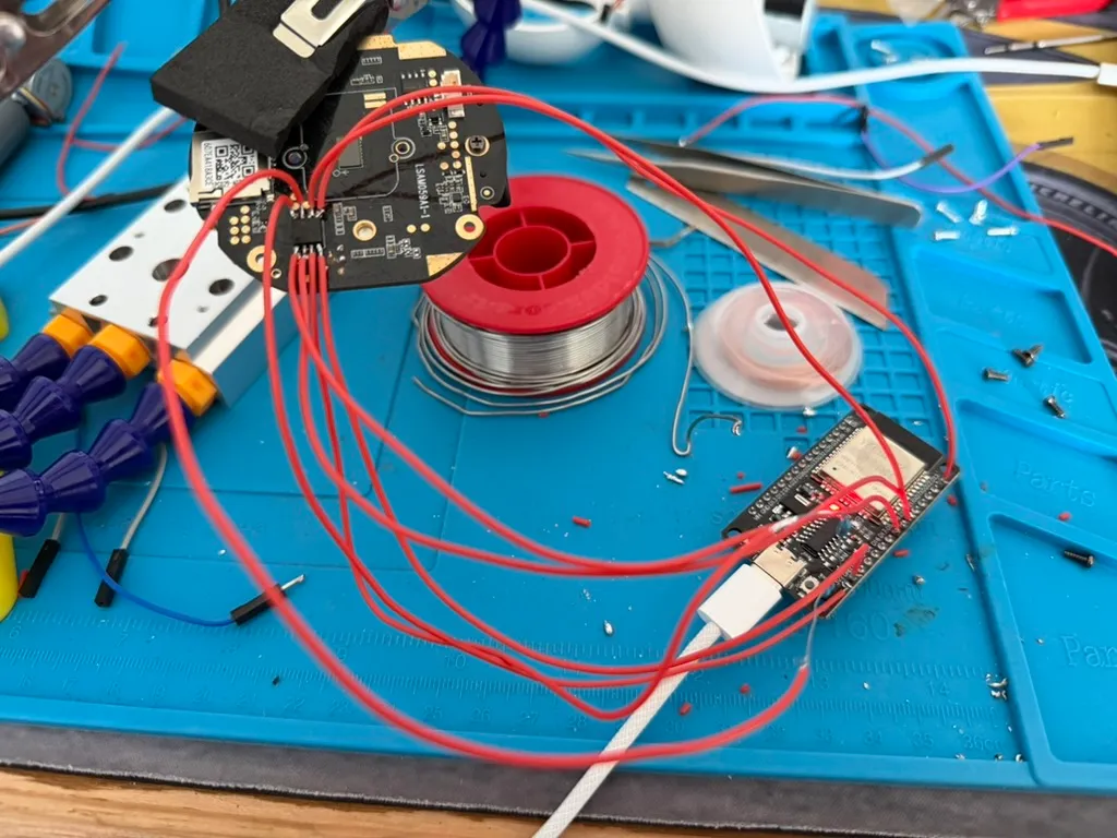
Two pins people forget: WP# and HOLD#. On this package they double as SIO2 and SIO3 — the extra data lines the SoC uses for quad reads. They need to sit high while you program, but here’s the part I learned the hard way: pull them high through 10 kΩ resistors, don’t tie them straight to 3.3 V. A hard tie wins the fight against the flash when you drive the bus, but it also stops the flash from driving those two lines when the SoC does its 54 MHz quad read at boot. My first attempt tied them solid, and afterwards the camera booted maybe one time in two — garbage in the quad burst every other power-on. Swapping the ties for 10 kΩ pull-ups fixed it completely. Weak enough that the flash still wins in quad mode, strong enough to hold the lines high while I write.
One warning worth repeating: this chip is a 3.3 V part. Feed it 5 V and you kill it. The ESP32 is 3.3 V native, which is exactly why it makes such a good flash programmer.
A note on reading in-circuit: keep the camera otherwise unpowered while you talk to the flash, and keep the ESP powered the whole time it’s attached. An unpowered ESP still on the bus is bad news — its GPIO clamp diodes conduct the moment a line rises, dragging the bus down and half-powering the chip through its own protection.
The ESP32 sketch
I didn’t want a heavyweight tool. A 25-series flash only needs a handful of one-byte commands: read an ID, read data, enable writes, erase, program a page, poll a status bit. So the whole thing is one Arduino sketch.
It parks the bus in high-Z when idle (so the camera can boot with the ESP still soldered on) and speaks a tiny binary protocol over serial: I for the JEDEC id, R/F to read, E/K to erase a sector or a 64 KB block, W/B to program, C for an on-device CRC32, and Z to drop off the bus.
// Fast SPI-NOR programmer for the IPC029A02 camera flash (MX25L128, C2 20 18).
// v2 - fixes an int/uint8_t truncation bug in v1 that could hang the sketch.
//
// WIRING (flash pin -> ESP32)
//   1 CS#        -> GPIO5
//   2 SO  /SIO1  -> GPIO19
//   3 WP# /SIO2  -> 10k to 3.3V   <-- resistor, NEVER a direct tie
//   4 GND        -> GND, shared with the camera
//   5 SI  /SIO0  -> GPIO23
//   6 SCLK       -> GPIO18
//   7 HOLD#/SIO3 -> 10k to 3.3V   <-- resistor, NEVER a direct tie
//   8 VCC        -> 3.3V
//
// Pins 3 and 7 are SIO2/SIO3 in quad mode. The flash must be able to drive
// them, so a hard tie to 3.3V breaks every burst read the SoC makes. Use 10k.
//
// Keep the ESP POWERED whenever the camera is powered; an unpowered ESP clamps
// the bus through its GPIO protection diodes regardless of this code. The bus
// is parked in high-Z when idle, and released automatically after 2s without
// a command, so the camera can boot with the ESP still attached.
//
// Camera POWERED OFF while erasing or writing.
//
// Protocol (all addresses/lengths big-endian):
//   P                          -> "PONG"          liveness, touches no SPI
//   I                          -> JEDEC id, hex
//   S                          -> status + config registers, hex
//   R <addr:4> <len:2>         -> len bytes, 0x03 read
//   F <addr:4> <len:2>         -> len bytes, 0x0B fast read at 40 MHz
//   C <addr:4> <len:4>         -> CRC32 of the range, 8 hex chars
//   E <addr:4>                 -> erase 4K sector   -> "OK"/"ERR"
//   K <addr:4>                 -> erase 64K block   -> "OK"/"ERR"
//   B <addr:4> <len:2> <data>  -> program len bytes -> "OK"/"ERR"
//   W <addr:4> <data:256>      -> program one page  -> "OK"/"ERR"
//   Z                          -> release the bus now

#include <SPI.h>

// If your USB-serial adapter can't do 921600, change this one line to 115200
// and pass --baud 115200 to flash_range.py.
#define BAUD          921600UL

#define PIN_CS    5
#define PIN_SCK   18
#define PIN_MISO  19
#define PIN_MOSI  23

#define CMD_ID        0x9F
#define CMD_READ      0x03
#define CMD_FASTREAD  0x0B
#define CMD_WREN      0x06
#define CMD_RDSR      0x05
#define CMD_RDCR      0x15
#define CMD_PP        0x02
#define CMD_SE        0x20
#define CMD_BE        0xD8

#define PAGE_SIZE     256
#define BULK_MAX      4096
#define OP_HZ         8000000UL
#define FAST_HZ       40000000UL
#define IDLE_RELEASE  2000          // ms of quiet before parking the bus

static bool     busHeld = false;
static uint32_t lastCmd = 0;
static uint8_t  buf[BULK_MAX];

static const uint32_t crc_tbl[16] = {
  0x00000000, 0x1DB71064, 0x3B6E20C8, 0x26D930AC,
  0x76DC4190, 0x6B6B51F4, 0x4DB26158, 0x5005713C,
  0xEDB88320, 0xF00F9344, 0xD6D6A3E8, 0xCB61B38C,
  0x9B64C2B0, 0x86D3D2D4, 0xA00AE278, 0xBDBDF21C
};

uint32_t crc32_update(uint32_t crc, const uint8_t *d, uint32_t n) {
  while (n--) {
    crc ^= *d++;
    crc = (crc >> 4) ^ crc_tbl[crc & 0x0F];
    crc = (crc >> 4) ^ crc_tbl[crc & 0x0F];
  }
  return crc;
}

void releaseBus() {
  if (busHeld) { SPI.end(); busHeld = false; }
  pinMode(PIN_CS,   INPUT);
  pinMode(PIN_SCK,  INPUT);
  pinMode(PIN_MOSI, INPUT);
  pinMode(PIN_MISO, INPUT);
}

void claimBus() {
  if (busHeld) return;
  pinMode(PIN_CS, OUTPUT);
  digitalWrite(PIN_CS, HIGH);
  SPI.begin(PIN_SCK, PIN_MISO, PIN_MOSI, PIN_CS);
  busHeld = true;
}

void csLow()  { digitalWrite(PIN_CS, LOW); }
void csHigh() { digitalWrite(PIN_CS, HIGH); }

uint8_t readReg(uint8_t opcode) {
  SPI.beginTransaction(SPISettings(OP_HZ, MSBFIRST, SPI_MODE0));
  csLow();
  SPI.transfer(opcode);
  uint8_t v = SPI.transfer(0);
  csHigh();
  SPI.endTransaction();
  return v;
}

void writeEnable() {
  SPI.beginTransaction(SPISettings(OP_HZ, MSBFIRST, SPI_MODE0));
  csLow();
  SPI.transfer(CMD_WREN);
  csHigh();
  SPI.endTransaction();
}

bool waitReady(uint32_t timeout) {
  uint32_t start = millis();
  while (readReg(CMD_RDSR) & 0x01)
    if (millis() - start > timeout) return false;
  return true;
}

void readData(uint32_t address, uint8_t *dst, uint32_t len, bool fast) {
  SPI.beginTransaction(SPISettings(fast ? FAST_HZ : OP_HZ, MSBFIRST, SPI_MODE0));
  csLow();
  SPI.transfer(fast ? CMD_FASTREAD : CMD_READ);
  SPI.transfer(address >> 16);
  SPI.transfer(address >> 8);
  SPI.transfer(address);
  if (fast) SPI.transfer(0);
  for (uint32_t i = 0; i < len; i++) dst[i] = SPI.transfer(0);
  csHigh();
  SPI.endTransaction();
}

bool eraseAt(uint32_t address, uint8_t opcode, uint32_t timeout) {
  if (!waitReady(5000)) return false;
  writeEnable();
  SPI.beginTransaction(SPISettings(OP_HZ, MSBFIRST, SPI_MODE0));
  csLow();
  SPI.transfer(opcode);
  SPI.transfer(address >> 16);
  SPI.transfer(address >> 8);
  SPI.transfer(address);
  csHigh();
  SPI.endTransaction();
  return waitReady(timeout);
}

bool programPage(uint32_t address, const uint8_t *src, uint16_t len) {
  if (!waitReady(5000)) return false;
  writeEnable();
  SPI.beginTransaction(SPISettings(OP_HZ, MSBFIRST, SPI_MODE0));
  csLow();
  SPI.transfer(CMD_PP);
  SPI.transfer(address >> 16);
  SPI.transfer(address >> 8);
  SPI.transfer(address);
  for (uint16_t i = 0; i < len; i++) SPI.transfer(src[i]);
  csHigh();
  SPI.endTransaction();
  return waitReady(5000);
}

void sendHexByte(uint8_t b) {
  const char *hex = "0123456789ABCDEF";
  Serial.write(hex[b >> 4]);
  Serial.write(hex[b & 15]);
}

// Blocking read of n bytes, big-endian. The int comparison here is the fix:
// casting Serial.available() to uint8_t made 256 look like 0 and hung v1.
bool readBE(uint8_t n, uint32_t *out, uint32_t timeout = 3000) {
  uint32_t v = 0, t0 = millis();
  for (uint8_t i = 0; i < n; i++) {
    while (Serial.available() <= 0) {
      if (millis() - t0 > timeout) return false;
    }
    v = (v << 8) | (uint8_t)Serial.read();
    t0 = millis();
  }
  *out = v;
  return true;
}

void setup() {
  Serial.setRxBufferSize(8192);
  Serial.begin(BAUD);
  delay(50);
  releaseBus();
  Serial.print("SPIFLASHER2 ready @");
  Serial.println(BAUD);
}

void loop() {
  if (busHeld && millis() - lastCmd > IDLE_RELEASE) releaseBus();

  if (Serial.available() <= 0) return;

  char cmd = Serial.read();
  lastCmd = millis();

  if (cmd == 'P') { Serial.println("PONG"); return; }

  if (cmd == 'Z') { releaseBus(); Serial.println("RELEASED"); return; }

  if (cmd != 'I' && cmd != 'S' && cmd != 'R' && cmd != 'F' &&
      cmd != 'C' && cmd != 'E' && cmd != 'K' && cmd != 'B' && cmd != 'W')
    return;                                   // ignore noise

  claimBus();
  uint32_t addr = 0, len = 0;

  if (cmd == 'I') {
    SPI.beginTransaction(SPISettings(OP_HZ, MSBFIRST, SPI_MODE0));
    csLow();
    SPI.transfer(CMD_ID);
    uint8_t a = SPI.transfer(0), b = SPI.transfer(0), c = SPI.transfer(0);
    csHigh();
    SPI.endTransaction();
    sendHexByte(a); sendHexByte(b); sendHexByte(c);
    Serial.println();
  }

  else if (cmd == 'S') {
    uint8_t sr = readReg(CMD_RDSR), cr = readReg(CMD_RDCR);
    sendHexByte(sr); sendHexByte(cr);
    Serial.println();
  }

  else if (cmd == 'R' || cmd == 'F') {
    if (!readBE(4, &addr) || !readBE(2, &len)) return;
    while (len) {
      uint32_t n = len > BULK_MAX ? BULK_MAX : len;
      readData(addr, buf, n, cmd == 'F');
      Serial.write(buf, n);
      addr += n; len -= n;
    }
  }

  else if (cmd == 'C') {
    if (!readBE(4, &addr) || !readBE(4, &len)) return;
    uint32_t crc = 0xFFFFFFFF;
    while (len) {
      uint32_t n = len > BULK_MAX ? BULK_MAX : len;
      readData(addr, buf, n, false);
      crc = crc32_update(crc, buf, n);
      addr += n; len -= n;
    }
    crc ^= 0xFFFFFFFF;
    sendHexByte(crc >> 24); sendHexByte(crc >> 16);
    sendHexByte(crc >> 8);  sendHexByte(crc);
    Serial.println();
  }

  else if (cmd == 'E' || cmd == 'K') {
    if (!readBE(4, &addr)) { Serial.println("ERR"); return; }
    bool ok = (cmd == 'E') ? eraseAt(addr, CMD_SE, 10000)
                           : eraseAt(addr, CMD_BE, 20000);
    Serial.println(ok ? "OK" : "ERR");
  }

  else if (cmd == 'B' || cmd == 'W') {
    if (!readBE(4, &addr)) { Serial.println("ERR"); return; }
    if (cmd == 'B') { if (!readBE(2, &len)) { Serial.println("ERR"); return; } }
    else            { len = PAGE_SIZE; }
    if (len == 0 || len > BULK_MAX) { Serial.println("ERR"); return; }

    uint32_t got = 0, t0 = millis();
    while (got < len) {
      if (Serial.available() > 0) { buf[got++] = Serial.read(); t0 = millis(); }
      else if (millis() - t0 > 3000) { Serial.println("ERR"); return; }
    }

    bool ok = true;
    uint32_t done = 0;
    while (done < len && ok) {
      uint32_t off = (addr + done) & (PAGE_SIZE - 1);
      uint32_t n = PAGE_SIZE - off;
      if (n > len - done) n = len - done;
      ok = programPage(addr + done, buf + done, n);
      done += n;
    }
    Serial.println(ok ? "OK" : "ERR");
  }

  lastCmd = millis();
}
First sanity check: ask for the ID. A Macronix MX25L12833F answers C2 20 18. Seeing that come back is the moment you know the wiring is right and the chip is talking to you.
$ printf 'I' > /dev/tty.usbserial-10
C22018
C2 is Macronix, 2018 is the 128-megabit density. Everything matched, so I moved on to the dump.
Dumping the firmware
The host side is a tiny Python script. It fast-reads the flash in 4 KB chunks and writes the whole 16 MB to a file.
import serial, struct

SIZE = 16 * 1024 * 1024
ser = serial.Serial('/dev/tty.usbserial-10', 921600, timeout=5)

def rd(addr, n):
    ser.write(b'F' + struct.pack('>IH', addr, n))
    return ser.read(n)

with open('dump.bin', 'wb') as f:
    for addr in range(0, SIZE, 4096):
        f.write(rd(addr, 4096))
print('read', SIZE, 'bytes')
I dumped it twice and compared the two files. If a hardware read is flaky, you find out here, before you waste an hour editing a corrupt image. My first dump was actually 907 bytes short and byte-shifted — a UART overrun, not a flash fault — so this check earns its keep:
$ cmp dump1.bin dump2.bin && echo "identical, good read"
identical, good read
Better still, check a dump against its own internal checksums. The kernel is packed in a uImage with a header CRC and a payload CRC; if those parse and match, the read is genuinely good, not just self-consistent. That’s the test that told me my second dump was trustworthy.
Back this file up now. This untouched dump is your undo button. As long as you keep it, there’s no way to permanently brick the camera, because you can always write the original straight back.
Reading the map
The exact layout comes from the SigmaStar MXP partition table near the start of the flash — a run of MXPT records, each with an offset, a size, and a name. Decoded, it looks like this:
IPL          0x00000000 0x00010000
IPL_CUST     0x00010000 0x0000f000
KEY_CUST     0x0001f000 0x00001000
MXPT         0x00020000 0x00001000
UBOOT        0x00030000 0x0001f000
UBOOT_ENV    0x0004f000 0x00001000
KERNEL       0x00050000 0x00200000   <- uImage
ROOTFS       0x00250000 0x00760000   <- mtdblock2, squashfs
DATA         0x009b0000 0x00630000
CONFIG       0x00fe0000 0x00010000
FACTORY      0x00ff0000 0x00010000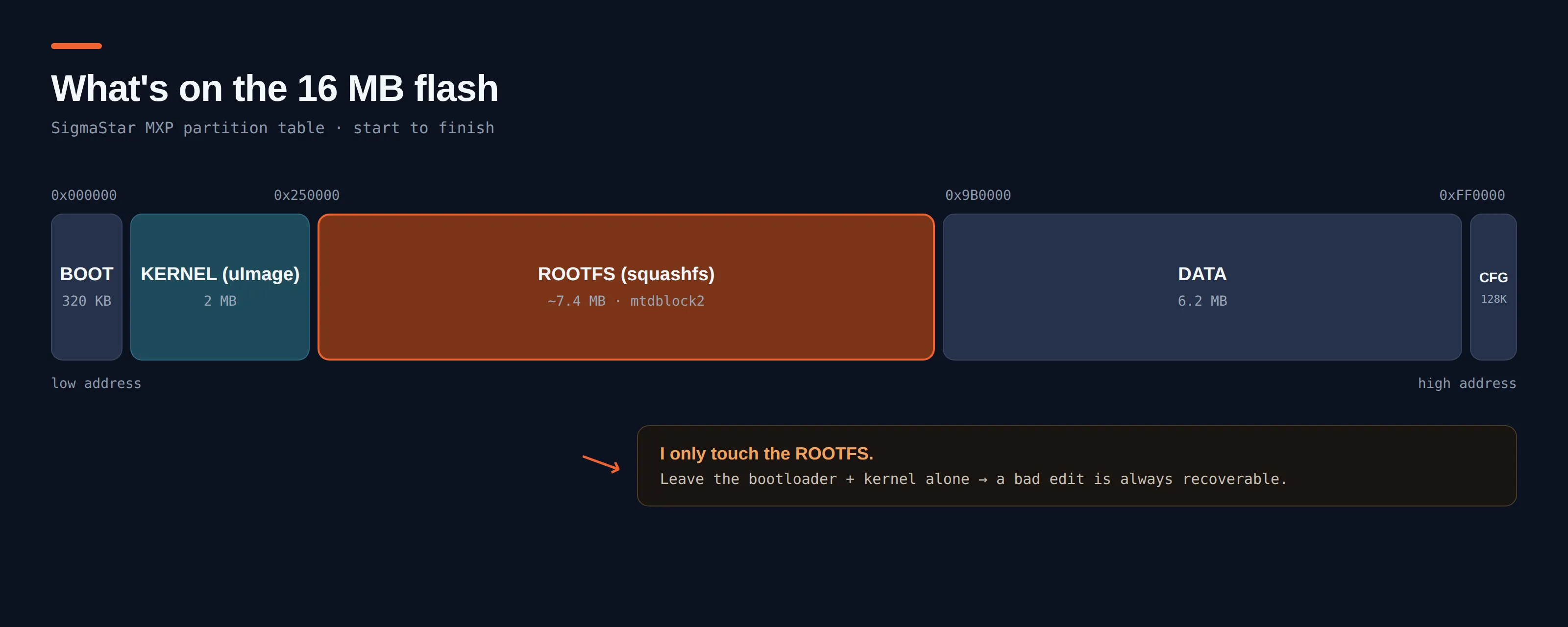
The line that matters is the squashfs at 0x250000. That’s the root filesystem — the actual Linux system: /etc, /bin, the startup scripts, everything. That’s where root access is won or lost.
And one rule keeps the whole thing safe: I only touch the rootfs. The bootloader and the kernel I leave completely alone. Mangle the rootfs and the worst case is a camera that boots and falls over, which I fix by writing my backup back. Mangle the bootloader and I’ve got a paperweight. So I don’t.
Getting into the filesystem — and the trap that bricked it once
I carved the squashfs region out of the dump and unpacked it. Two things you must not skip.
First, read the superblock with unsquashfs -s and note the compressor and block size. You have to repack with the exact same settings, or the kernel will refuse to mount your version.
Second — and this one cost me a full brick — extract and repack squashfs on Linux, as root. Not on macOS. My first modified image booted the ROM loader, the bootloader, and the kernel, then died the instant it handed off to userspace, with no console to say why. When I finally compared the two filesystems offline, the modified one had 309 files where the original had 1617, and /linuxrc — the thing bootargs runs as init — was zero bytes. The culprit was a macOS unsquashfs that read only the first block of each file and stopped. On the camera that’s an instant kernel panic. On Linux, as root, everything round-trips cleanly.
# on a Linux box, as root
dd if=dump.bin of=rootfs.sqsh bs=4096 skip=$((0x250000 / 4096)) \
   count=$((0x760000 / 4096))

unsquashfs -s rootfs.sqsh          # note: xz, 128K block
unsquashfs -d rootfs rootfs.sqsh   # -> a normal folder, mine to edit
Now I had a normal folder called rootfs holding the camera’s entire Linux system.
Backdooring the rootfs
“Backdoor” sounds dramatic. In practice it’s one extra line in the boot script that hands me a root shell on the network. But three small realities on this box shape exactly what that line has to say:
- The rootfs BusyBox has no
telnetdapplet.strings bin/busybox | grep -x telnetdcomes back empty. So I drop a staticbusybox-armv7lonto a FAT32 SD card and call that — the built-in one can’t help me. - The card is mounted late, and might be missing. So the line backgrounds itself and retries for a while instead of stalling the boot.
- The root password in
/etc/shadowis unknown, and I’ve no interest in cracking it.telnetd -l /bin/shskips/bin/loginentirely and hands every connection a shell — no prompt, no password.
The startup script is rootfs/etc/init.d/rcS. I appended this block to the very end:
# --- my block, added to the end of /etc/init.d/rcS ---
(
	i=0
	while [ $i -lt 10 ]; do
		for d in /mnt/sdcard /mnt/media/mmcblk0p1 /mnt/media/mmcblk0; do
			if [ -x "$d/busybox-armv7l" ]; then
				"$d/busybox-armv7l" telnetd -l /bin/sh
				exit 0
			fi
		done
		i=$((i+1))
		sleep 3
	done
) &
That’s an unauthenticated root shell on the LAN — perfect for bring-up, and something you take back out once you’ve got what you need.
One gotcha if you go the SD-card route: the bootloader also looks for a signed tf_update.img on the card before Linux runs, and only renames it after a successful boot. So keep two cards — a recovery card with tf_update.img only, and a working card with busybox-armv7l only — or a card holding both will reflash stock on every power cycle and fight you forever.
Repacking, and the one rule that matters
Repack with the same compressor and block size the superblock reported. I also pass -all-root so every file is owned by root in the new image, no matter what user I edited as.
mksquashfs rootfs rootfs-new.sqsh -comp xz -b 131072 -noappend -all-rootThen the one hard constraint: the new filesystem has to fit the slot the old one lived in. The ROOTFS partition runs from 0x250000 to 0x9b0000, which is 0x760000 — about 7.4 MB. As long as rootfs-new.sqsh isn’t bigger than that, I’m fine. A few extra lines of shell shrink nothing and grow nothing worth worrying about, so it fit easily.
$ ls -l rootfs-new.sqsh
# must be <= 0x760000 (~7.4 MB). Mine was well under.
Reassembling the full image
Now I rebuild the complete 16 MB image: take the original dump, overwrite only the rootfs region with my new squashfs, and pad out to the region length with 0x00. The bootloader, the kernel, DATA, CONFIG and FACTORY all stay byte-for-byte identical to the original.
REGION_START = 0x250000
REGION_LEN   = 0x760000   # ~7.4 MB

new_rootfs = open('rootfs-new.sqsh', 'rb').read()
assert len(new_rootfs) <= REGION_LEN, "rootfs too big for its slot"

img = bytearray(open('dump.bin', 'rb').read())          # the untouched backup
img[REGION_START:REGION_START + len(new_rootfs)] = new_rootfs
open('firmware_telnet.bin', 'wb').write(img)
print('patched image is', len(img), 'bytes')
Two quick checks before this goes anywhere near the chip. Confirm the squashfs magic still sits at 0x250000, and prove the bootloader and kernel are untouched:
$ cmp <(head -c $((0x250000)) dump.bin) \
      <(head -c $((0x250000)) firmware_telnet.bin) \
    && echo "bootloader + kernel untouched"
bootloader + kernel untouched
Why the camera can’t say no
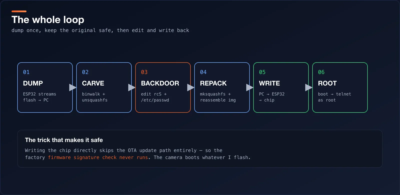
This works even though the firmware is “signed”, and the reason is almost boring. When the camera updates itself the normal way — an official tf_update.img over SD, or OTA — the bootloader verifies an Ed25519 signature against a key burned into the SoC’s eFuses and rejects anything the vendor didn’t bless. I fed it a self-built image over SD once, just to see; it printed Verifying signature using libsodium ... Failed and refused. You can’t sign your own.
But I’m not using that path at all. I’m writing raw bytes onto the flash chip with an ESP32, and nothing in that chain checks a signature. The CPU powers on, the bootloader loads the kernel, the kernel mounts whatever squashfs is sitting at 0x250000, and that squashfs is now mine. The signature check only guards the update door. Going in through the hardware walks around it.
Writing it back
This is the part everyone worries about. The host script erases the sectors the image covers, programs it page by page, then reads every page back and compares. Point it at the modified image with --program:
$ python flash.py ../Firmware-scripts/firmware_telnet.bin --program
Image: ../Firmware-scripts/firmware_telnet.bin
Size:  16,777,216 bytes
SHA256: 4b1e…
Flash ID: C22018

WARNING: FLASH WILL BE ERASED/PROGRAMMED.
Starting in 5 seconds...
Erasing: 4096/4096
Erase complete.
Writing: 65536/65536
Write complete.
Verifying...
Verifying: 65536/65536

VERIFY SUCCESS.
The programmed region matches the image.
Run it once without --program first — that’s a dry run: it confirms the flash ID and prints the SHA256 of what would be written, and touches nothing. PORT and BAUD are set at the top of flash.py; match them to your adapter. And don’t skip the verify at the end — VERIFY SUCCESS is the line that says the flash is exactly what you meant to write and it’s safe to close the camera up.
Powering on
I took the leads off, put the camera back together, and gave it power like nothing had happened. It booted normally — same startup time, same behaviour — except now it was quietly running a root shell on the network.
$ telnet 192.168.1.50
Connected to 192.168.1.50.

/ # whoami
root
/ # cat /proc/cpuinfo | head -1
Hardware : Sigmastar Infinity6root. From a dead RX pad to a root prompt, without ever getting the serial console to talk back.
What I did differently from the tutorial
The sungurlabs writeup is a great map, and it’s where I started. But its whole route runs through the serial console: interrupt the bootloader, type commands, dump and reflash from there. That needs a working RX pin, and mine was gone.
So everything here talks straight to the flash chip instead:
- No serial console. The ESP32 is wired directly to the SOIC-8 flash, not to the camera’s CPU.
- The ESP32 is the programmer. A short Arduino sketch, not a dedicated tool, does the reading and writing.
- Only the rootfs changes. The bootloader and kernel are never written, so a bad edit is always recoverable from the backup.
Same destination, completely different door.
Coming in part two
Root is just the key. The interesting part is what you do once you’re inside — and that’s a whole post of its own.
In part two I’ll pull a live RTSP stream straight off the camera, cut the cloud out for good, and make it a plain local device I can point anything at — no app, no account, no video leaving the house. That’s the payoff, and it’s coming next.
A few honest warnings
- Do this only to hardware you own. This is my camera, on my bench, on my network.
- 3.3 V only. 5 V will kill the flash chip.
- 10 kΩ pull-ups on WP# and HOLD#, never a hard tie — or you’ll fight the SoC’s quad reads and get an intermittent boot.
- Keep the original dump. It’s your one true undo. Guard it.
- Extract and repack squashfs on Linux, as root. macOS will hand you a silently truncated filesystem and a bricked camera.
- Don’t touch the bootloader or kernel unless you enjoy paperweights. Rootfs edits are recoverable; bootloader mistakes often aren’t.
If you’re trying something similar and it’s misbehaving, or you just want to swap hardware-hacking stories, get in touch. I’m always happy to help someone else get root on their own gear.
Follow me on LinkedIn, and let’s keep taking our devices back. 🔧📷🔓
Follow along. New posts show up on the RSS feed. I also share my projects on GitHub, MakerWorld and LinkedIn.